Governor Type 1
A linearized model of a hydraulic turbine with an IEEE type 1 speed controller.
blockType: SubSystem
|
Path in the library: |

Description
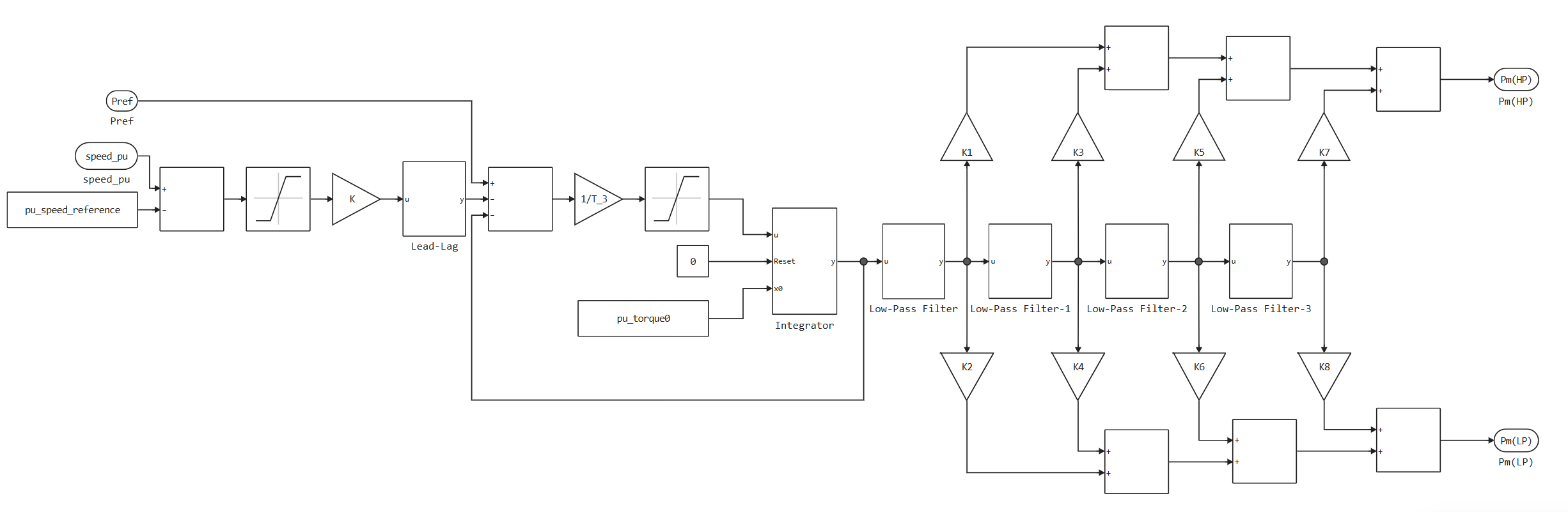
Block Governor Type 1 It is a model of a steam turbine with an IEEEG1 speed controller.
This unit allows you to simulate a two-shaft turbine and has two sets of fractions.:
-
LP Fraction, K_2, LP Fraction, K_4, LP Fraction, K_6, LP Fraction, K_8 for low pressure (LP).
-
HP Fraction, K_1, HP Fraction, K_3, HP Fraction, K_5, HP Fraction, K_7 for high pressure (HP).
This diagram illustrates the general structure of the block.:
Ports
Input
#
ω
—
turbine rotation speed
scalar
Details
The turbine speed in relative units, set as a scalar.
| Data types |
|
| Complex numbers support |
No |
#
Pref
—
displacement of the reference speed
scalar
Details
The offset applied to setting the load speed of the turbine regulator is returned as a scalar. Connect this port to the output port Pref of the turbine load regulator unit, for example, the Controller LCFB1
| Data types |
|
| Complex numbers support |
No |
Output
#
Pm(HP)
—
high pressure mechanical power
scalar
Details
High-pressure mechanical power is returned as a scalar.
| Data types |
|
| Complex numbers support |
No |
#
Pm(LP)
—
low pressure mechanical power
scalar
Details
Low-pressure mechanical power returned as a scalar.
| Data types |
|
| Complex numbers support |
No |
Parameters
Main group
# Speed reference, pu — setting the speed
Details
The speed standard in relative units.
| Default value |
|
| Program usage name |
|
| Evaluatable |
Yes |
# Initial torque, pu — initial torque
Details
The initial torque per unit at the beginning of the simulation.
| Default value |
|
| Program usage name |
|
| Evaluatable |
Yes |
Main
# Governor gain K, pu — regulator gain factor
Details
The gain of the regulator.
| Default value |
|
| Program usage name |
|
| Evaluatable |
Yes |
# Lag time constant T_1, s — the delay time constant of the regulator
Details
The equivalent delay time constant. This parameter is associated with the block indicated in the diagram as Lead-Lag. Set this parameter to 0 if the additional lag dynamics is negligible.
| Default value |
|
| Program usage name |
|
| Evaluatable |
Yes |
# Lead time constant T_2, s — the time constant of the regulator advance
Details
The equivalent advance time constant. This parameter is associated with the block indicated in the diagram as Lead-Lag. Set this parameter to 0 if the additional advance dynamics is negligible.
| Default value |
|
| Program usage name |
|
| Evaluatable |
Yes |
# Valve position time constant T_3, s — valve position time constant
Details
The time constant of the valve position.
| Default value |
|
| Program usage name |
|
| Evaluatable |
Yes |
# Maximum valve opening rate U_o, pu/s — maximum valve opening speed
Details
The maximum opening speed of the valve.
| Default value |
|
| Program usage name |
|
| Evaluatable |
Yes |
# Maximum valve closing rate U_c, pu/s — maximum closing speed of the valve
Details
The maximum closing speed of the valve.
| Default value |
|
| Program usage name |
|
| Evaluatable |
Yes |
# Maximum valve opening, on MW capability P_max, pu — maximum valve opening O. E., at power P-max
Details
Maximum valve opening O. E., at power P-max.
| Default value |
|
| Program usage name |
|
| Evaluatable |
Yes |
# Minimum valve opening, on MW capability P_min, pu — Minimum valve opening O. E., at power P-min
Details
Minimum valve opening O. E., at power P-min.
| Default value |
|
| Program usage name |
|
| Evaluatable |
Yes |
# Time constant for steam inlet T_4, s — the time constant of the incoming steam
Details
The steam intake time constant. This parameter is associated with the block indicated in the diagram as Low-Pass Filter.
| Default value |
|
| Program usage name |
|
| Evaluatable |
Yes |
# HP fraction K_1 — the power level of the high-pressure shaft, K_1
Details
The degree of power of the high-pressure shaft after the first passage of the boiler.
| Default value |
|
| Program usage name |
|
| Evaluatable |
Yes |
# LP fraction K_2 — the power level of the low-pressure shaft, K_2
Details
The power level of the low-pressure shaft after the first passage of the boiler.
| Default value |
|
| Program usage name |
|
| Evaluatable |
Yes |
# Time constant for second boiler pass T_5, s — time constant for the second boiler pass
Details
The time constant of the second boiler pass. This parameter is associated with the block indicated in the diagram as Low-Pass Filter1.
| Default value |
|
| Program usage name |
|
| Evaluatable |
Yes |
# HP fraction, K_3 — the power level of the high-pressure shaft, K_3
Details
The degree of power of the high-pressure shaft after the second passage of the boiler.
| Default value |
|
| Program usage name |
|
| Evaluatable |
Yes |
# LP fraction, K_4 — the power level of the low-pressure shaft, K_4
Details
The power level of the low-pressure shaft after the second passage of the boiler.
| Default value |
|
| Program usage name |
|
| Evaluatable |
Yes |
# Time constant for third boiler pass T_6, s — time constant for the third boiler pass
Details
The time constant of the third boiler pass. This parameter is associated with the block indicated in the diagram as Low-Pass Filter2.
| Default value |
|
| Program usage name |
|
| Evaluatable |
Yes |
# HP fraction, K_5 — the power level of the high-pressure shaft, K_5
Details
The degree of power of the high-pressure shaft after the third passage of the boiler.
| Default value |
|
| Program usage name |
|
| Evaluatable |
Yes |
# LP fraction, K_6 — power level of the low-pressure shaft, K_6
Details
The power level of the low-pressure shaft after the third passage of the boiler.
| Default value |
|
| Program usage name |
|
| Evaluatable |
Yes |
# Time constant for fourth boiler pass T_7, s — the time constant for the fourth boiler pass
Details
The time constant of the fourth boiler pass. This parameter is associated with the block indicated in the diagram as Low-Pass Filter3.
| Default value |
|
| Program usage name |
|
| Evaluatable |
Yes |
# HP fraction, K_7 — the power level of the high-pressure shaft, K_7
Details
The degree of power of the high-pressure shaft after the fourth passage of the boiler.
| Default value |
|
| Program usage name |
|
| Evaluatable |
Yes |
# LP fraction, K_8 — power level of the low-pressure shaft, K_8
Details
The power level of the low-pressure shaft after the fourth passage of the boiler.
| Default value |
|
| Program usage name |
|
| Evaluatable |
Yes |
# Deadband — the width of the dead zone
Details
The specified width of the deadband is from +deadband to -deadband.
| Default value |
|
| Program usage name |
|
| Evaluatable |
Yes |
Literature
-
"Dynamic Models for Steam and Hydro Turbines in Power System Studies, IEEE Transactions on Power Apparatus and Systems." Vol. PAS-92, Number 6, 1973, pp. 1904–1915.
-
"Task Force on Turbine-Governor Modeling, Dynamic models for turbine-governors in power system studies", IEEE Power Energy Society, January 2013.
-
"IEEE Guide for the Application of Turbine Governor Systems for Hydroelectric Generating Units", IEEE Std 1207-2011.