Hydraulic Turbine and Governor
A model of a hydraulic turbine and a proportional-integral-derivative (PID) control system.
blockType: SubSystem
|
Path in the library: |

Description
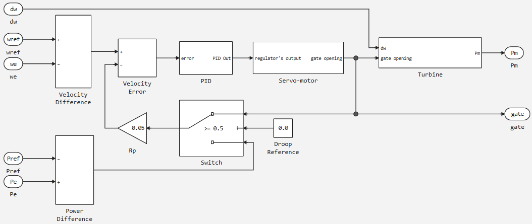
The Hydraulic Turbine and Governor block implements a non-linear hydraulic turbine model, a PID controller system and a servo drive [1]:
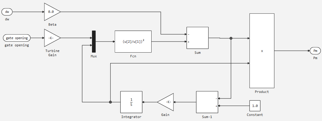
The hydraulic turbine is modelled by the following nonlinear system:
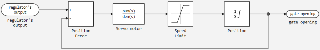
The gate servo is modelled by a second order system:
Ports
Input
#
ωe
—
actual machine speed
scalar
Details
The actual speed of the machine in relative units.
| Data types |
|
| Complex numbers support |
No |
#
Δω
—
velocity deviation
scalar
Details
Velocity deviation in relative units.
| Data types |
|
| Complex numbers support |
No |
#
ωref
—
reference speed
scalar
Details
Reference velocity in relative units.
| Data types |
|
| Complex numbers support |
No |
#
gate
—
gate opening
scalar
Details
Shutter opening in relative units.
| Data types |
|
| Complex numbers support |
No |
#
Pref
—
reference mechanical power
scalar
Details
Reference mechanical power in relative units. This input can be omitted if you want to use the gate position as input to the feedback circuit instead of power rejection.
| Data types |
|
| Complex numbers support |
No |
Output
#
Pm
—
mechanical power
scalar
Details
Mechanical power for the Synchronous Machine unit in relative units.
| Data types |
|
| Complex numbers support |
No |
#
Pe0
—
actual electrical power of the machine
scalar
Details
The actual electrical power of the machine in relative units. This input can be omitted if you wish to use the gate position as an input to the feedback circuit instead of power rejection.
| Data types |
|
| Complex numbers support |
No |
Parameters
Main
# Servo-motor [Ka Ta(s)] — gain and time constant of the first-order system
Details
The gain and time constant , in seconds (s), of the first-order system representing the servo drive.
| Default value |
|
| Program usage name |
|
| Evaluatable |
Yes |
# Gate opening limits [gmin(pu) gmax(pu) vgmin(pu/s) vgmax(pu/s)] — shutter opening limits
Details
Limits and (pu) imposed on the gate opening and and ( ) imposed on the gate speed.
| Default value |
|
| Program usage name |
|
| Evaluatable |
Yes |
# Permanent droop and regulator [Rp Kp Ki Kd Td(s)] — constant throttle and regulator
Details
The static gain of the regulator is equal to the inverse of the constant decay in the feedback circuit. The PID controller has proportional gain , integral gain and derivative gain . The high-frequency gain of the PID controller is limited by a first-order low-pass filter with a time constant (s).
| Default value |
|
| Program usage name |
|
| Evaluatable |
Yes |
# Hydraulic turbine [beta Tw(s)] — speed deviation damping coefficient and water start-up time
Details
Speed deviation damping factor and water start-up time (s).
| Default value |
|
| Program usage name |
|
| Evaluatable |
Yes |
# Droop reference (0=power error, 1=gate opening) — feedback loop input
Details
Feedback loop input: gate position (1) or electrical power deviation (0).
| Default value |
|
| Program usage name |
|
| Evaluatable |
Yes |
Initial Values
# Initial mechanical power, pu — initial mechanical power
Details
Initial mechanical power in relative units.
| Default value |
|
| Program usage name |
|
| Evaluatable |
Yes |