Governor Type 3
A linearized model of a hydraulic turbine with an IEEE type 3 speed controller.
blockType: SubSystem
|
Path in the library: |

Description
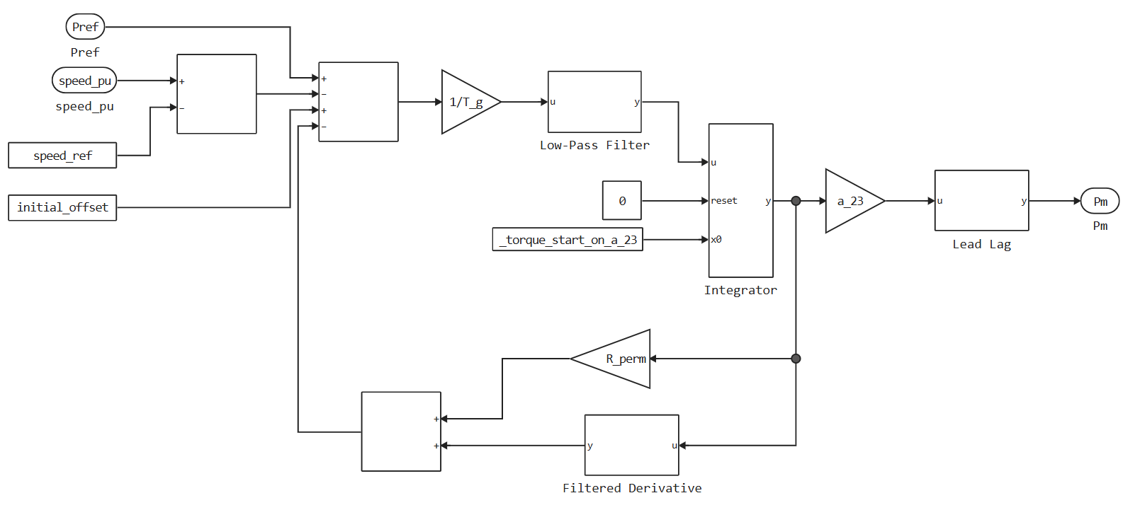
Block Governor Type 3 It is a model of an IEEEG3 hydraulic turbine regulator with pressure duct dynamics.
This unit has a more detailed regulator model than the Governor Type 1 unit, and uses a linearized turbine model, or water column model, and pressure duct dynamics.
This diagram illustrates the general structure of the block.:
Ports
Input
#
ω
—
turbine rotation speed
scalar
Details
The turbine speed in relative units, set as a scalar.
| Data types |
|
| Complex numbers support |
No |
#
Pref
—
displacement of the reference speed
scalar
Details
The offset applied to setting the load speed of the turbine regulator is returned as a scalar.
Connect this port to the output port Pref of the turbine load regulator unit, for example, the Controller LCFB1.
| Data types |
|
| Complex numbers support |
No |
Output
#
Pm
—
mechanical power
scalar
Details
Mechanical power is returned as a scalar.
| Data types |
|
| Complex numbers support |
No |
Parameters
Main
# Speed reference, pu — speed setting
Details
The speed standard in relative units.
| Default value |
|
| Program usage name |
|
| Evaluatable |
Yes |
# Initial torque, pu — initial torque
Details
The initial torque in relative units at the beginning of the simulation.
| Default value |
|
| Program usage name |
|
| Evaluatable |
Yes |
# Sample time (-1 for inherited) — sample time
Details
Time between consecutive block executions. During execution, the block produces output and, if necessary, updates its internal state.
-
For inherited discrete-time operation, set this parameter to
-1. -
For discrete-time operation, set this parameter to a positive integer.
-
For continuous-time operation, set this parameter to
0.
If this block is in a masked subsystem or variant subsystem that supports switching between continuous and discrete operation modes, increase this parameter value to ensure correct switching between continuous and discrete block implementations.
For more information, see Masks in Engee
| Default value |
|
| Program usage name |
|
| Evaluatable |
Yes |
Main
# Gate servomotor time constant T_g, s — time constant for the servo motor of the hydraulic turbine guiding device
Details
The time constant for the servo motor of the hydraulic turbine guidance device.
| Default value |
|
| Program usage name |
|
| Evaluatable |
Yes |
# Pilot value time constant T_p, s — the time constant of the control signal
Details
The time constant of the control signal. This parameter is associated with the block indicated in the diagram as Low-Pass Filter.
| Default value |
|
| Program usage name |
|
| Evaluatable |
Yes |
# Opening gate rate limit U_o, pu/s — shutter speed limit
Details
The limit of the shutter opening speed is one. This parameter is associated with the block indicated in the diagram as Low-Pass Filter.
| Default value |
|
| Program usage name |
|
| Evaluatable |
Yes |
# Closing gate rate limit U_c, pu/s — shutter speed limit
Details
The limit of the shutter closing speed is one. This parameter is associated with the block indicated in the diagram as Low-Pass Filter.
| Default value |
|
| Program usage name |
|
| Evaluatable |
Yes |
# Maximum gate position, on MVA capability P_max, pu — maximum valve opening O. E., at power P-max
Details
Maximum valve opening O. E., at power P-max.
| Default value |
|
| Program usage name |
|
| Evaluatable |
Yes |
# Minimum gate position, on MVA capability P_min, pu — minimum valve opening O. E., at power P-min
Details
Minimum valve opening O. E., at power P-min.
| Default value |
|
| Program usage name |
|
| Evaluatable |
Yes |
# Permanent speed droop coefficient R_perm, pu — the coefficient of static velocity in relative units
Details
The coefficient of static velocity in relative units.
| Default value |
|
| Program usage name |
|
| Evaluatable |
Yes |
# Transient speed droop coefficient R_temp, pu — the coefficient of speed reduction during the transition period
Details
The coefficient of reduction of the transition velocity in relative units. This parameter is associated with the block indicated in the diagram as Filtered Derivative.
| Default value |
|
| Program usage name |
|
| Evaluatable |
Yes |
# Governor time constant T_r, s — the time constant of the regulator
Details
The time constant of the regulator. This parameter is associated with the block indicated in the diagram as Filtered Derivative.
| Default value |
|
| Program usage name |
|
| Evaluatable |
Yes |
# Water starting time constant T_w, s — water start time constant
Details
The time constant of inertia of water. This parameter is associated with the block indicated in the diagram as Lead-Lag.
| Default value |
|
| Program usage name |
|
| Evaluatable |
Yes |
# Penstock coefficient a_11 — shutter dynamics coefficient a_11
Details
Shutter dynamics coefficient 11. This parameter is associated with the block indicated in the diagram as Lead-Lag.
| Default value |
|
| Program usage name |
|
| Evaluatable |
Yes |
# Penstock coefficient a_13 — shutter dynamics coefficient a_13
Details
The shutter dynamics coefficient a_13. This parameter is associated with the block indicated in the diagram as Lead-Lag.
| Default value |
|
| Program usage name |
|
| Evaluatable |
Yes |
# Penstock coefficient a_21 — shutter dynamics coefficient a_21
Details
Shutter dynamics coefficient a_21. This parameter is associated with the block indicated in the diagram as Lead-Lag.
| Default value |
|
| Program usage name |
|
| Evaluatable |
Yes |
# Penstock coefficient a_23 — shutter dynamics coefficient a_23
Details
The shutter dynamics coefficient a_23. This parameter is associated with the block indicated in the diagram as Lead-Lag.
| Default value |
|
| Program usage name |
|
| Evaluatable |
Yes |