Steam Turbine and Governor
A model of a speed control system, a steam turbine, and a shaft pipeline.
blockType: SubSystem
|
Path in the library: |

Description
Block Steam Turbine and Governor It implements a single-shaft multi-cylinder steam turbine unit, including a speed control system, a four-stage steam turbine and a shaft line with four rotors.
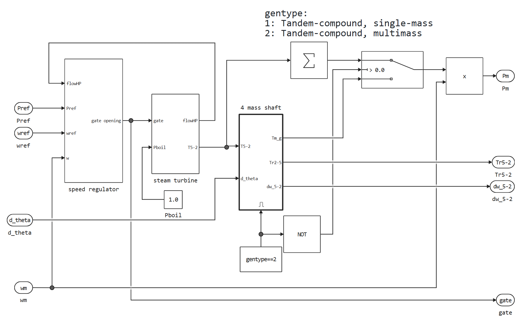
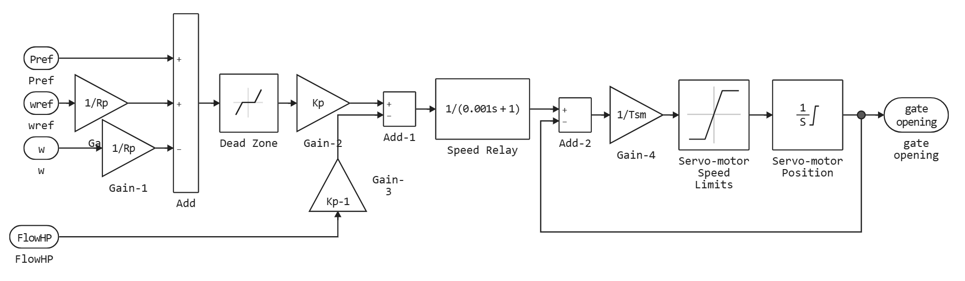
The speed control system consists of a P-controller, a speed relay and a servo that controls the shutter opening.
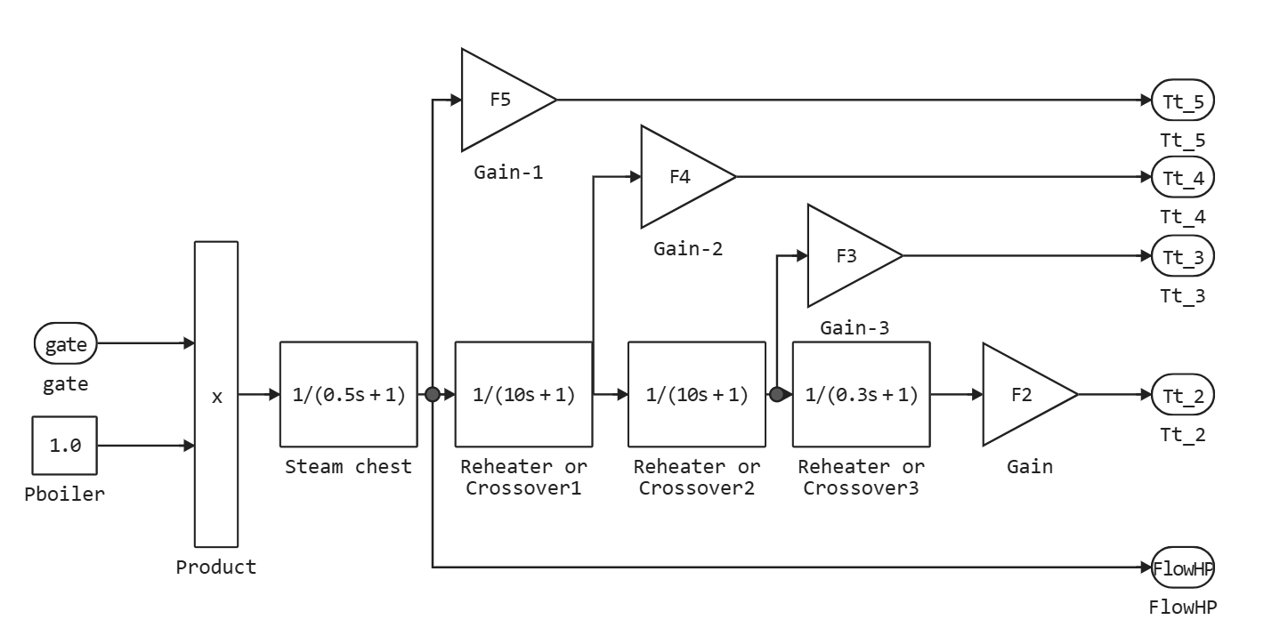
A steam turbine consists of four stages, each of which is modeled by a first-order transfer function. The first stage is a steam boiler, while the other three stages are either regenerative heaters or cross-piping. The boiler is not modeled, the pressure in the boiler is constant and amounts to 1 O.E. The coefficients (fractions) of the turbine torque They are used to distribute turbine power between different stages of the shaft pipeline.
The shaft line simulates a system of four masses, which is connected to the mass in the synchronous machine model, which gives a total of five masses. The mass of the machine is indicated as mass 1. The mass in the steam turbine and regulator block that is closest to the mass of the machine is mass 2, and the mass that is furthest from the machine is mass 5. The shaft line is characterized by mass inertia , damping coefficients and stiffness coefficients . If it is necessary to simulate a single-mass shaft line, the entire shaft line subsystem of four masses in the steam turbine block and the regulator will be disconnected, and all the torque from the turbine will be summed up and applied to the mass of the machine.
Ports
Input
#
ωref
—
speed setting
scalar
Details
Reference speed in relative units. It is usually connected to the Constant block with the value 1.0.
| Data types |
|
| Complex numbers support |
No |
#
Pref
—
mechanical power setting
scalar
Details
The reference mechanical power in relative units. It is set to a constant value corresponding to the initial active power consumed from the synchronous machine unit connected to the steam turbine and regulator unit.
| Data types |
|
| Complex numbers support |
No |
#
ωm
—
generator speed
scalar
Details
Generator speed in relative units. This is one of the signals in the last output of the synchronous machine model.
| Data types |
|
| Complex numbers support |
No |
#
Δθ
—
angular deviation of generator power
scalar
Details
Angular deviation of the generator power. It is also one of the signals at the last output of the synchronous machine model.
| Data types |
|
| Complex numbers support |
No |
Output
#
Δω5-2
—
deviation of mass velocity
vector
Details
The deviation of the velocity of masses 5, 4, 3 and 2 in relative units.
| Data types |
|
| Complex numbers support |
No |
#
Tr5-2
—
electromagnetic moments transmitted to the masses
vector
Details
Electromagnetic moments in relative units transmitted by masses 5, 4, 3 and 2.
| Data types |
|
| Complex numbers support |
No |
#
gate
—
opening the shutter
scalar
Details
Shutter opening in relative units.
| Data types |
|
| Complex numbers support |
No |
#
Pm
—
mechanical power
scalar
Details
Mechanical power for the Synchronous Machine unit in relative units.
| Data types |
|
| Complex numbers support |
No |
Parameters
Main
#
Generator type —
type of rotor
Tandem-Compound (single mass) | Tandem-Compound (multi-mass)
Details
Rotor type: single-mass or multi-mass single-shaft multi-cylinder.
If a single-mass system is selected, the multi-mass shaft subsystem in the Steam Turbine and Governor unit is disabled, and the turbine torques are summed and applied to the single-mass system in the Synchronous Machine unit.
| Values |
|
| Default value |
|
| Program usage name |
|
| Evaluatable |
Yes |
# Regulator gain, perm. droop, dead zone [Kp Rp(pu) Dz(pu)] — gain factor, static coefficient, and dead zone width
Details
Gain factor , constant decline in relative units, and the width of the dead zone in relative units. Set the gain value to 3 if you want to use a steam flow feedback loop. Otherwise, set the value 1.
| Default value |
|
| Program usage name |
|
| Evaluatable |
Yes |
# Speed relay and servo-motor time constants [Tsr Tsm], s — time constants of the shutter speed relay and servo
Details
Time constants of the speed relay and the gate servo motor in seconds.
| Default value |
|
| Program usage name |
|
| Evaluatable |
Yes |
# Gate opening limits [vgmin(pu/s) vgmax(pu/s) gmin(pu) gmax(pu)] — shutter opening limits
Details
Minimum and maximum shutter opening speed and in relative units per second, as well as the minimum and maximum shutter openings and in relative units.
| Default value |
|
| Program usage name |
|
| Evaluatable |
Yes |
# Nominal speed of synchronous machine, rpm — synchronous generator speed
Details
Synchronous speed of the generator in rpm, powered by a steam turbine.
| Default value |
|
| Program usage name |
|
| Evaluatable |
Yes |
# Steam turbine time constants [T2 T3 T4 T5], s — turbine time constants
Details
Turbine time constants from before in seconds. They are numbered sequentially with the fractions of the turbine torque and the mass number, for example, — the time constant of the first stage of the turbine, which simulates a steam chamber.
| Default value |
|
| Program usage name |
|
| Evaluatable |
Yes |
# Turbine torque fractions [F2 F3 F4 F5] — turbine torque fractions
Details
The proportion of turbine torque from before . The sum of the elements of this vector should be equal to 1 otherwise, an error message will appear. The numbers of the fractions correspond to the numbers of the masses, i.e. — this is the fraction of the torque applied to the mass of 2 multi-mass shafts.
| Default value |
|
| Program usage name |
|
| Evaluatable |
Yes |
# Coeff. of inertia [H2 H3 H4 H5], s — inertia coefficients
Details
Inertia coefficients from before seconds are related to the masses of the multi-mass shaft.
Dependencies
To use this parameter, set the Generator type parameter to Tandem-compound (multi-mass).
| Default value |
|
| Program usage name |
|
| Evaluatable |
Yes |
# Stiffness coeff. [K12 K23 K34 K45], pu/rad — stiffness coefficients
Details
Stiffness coefficients from before in relative units per radian, related to the masses of the multi-mass shaft, i.e. corresponds to the stiffness coefficient between masses 1 and 2, and so on.
Dependencies
To use this parameter, set the Generator type parameter to Tandem-compound (multi-mass).
| Default value |
|
| Program usage name |
|
| Evaluatable |
Yes |
# Damping factors [D2 D3 D4 D5], pu_T/pu_dw — damping coefficients
Details
Damping coefficients from before , defined as the ratio of torque in relative units and velocity deviations in relative units related to the masses of a multi-mass shaft.
Dependencies
To use this parameter, set the Generator type parameter to Tandem-compound (multi-mass).
| Default value |
|
| Program usage name |
|
| Evaluatable |
Yes |
Initial Values
# Initial power Pm0, pu — initial mechanical power
Details
Initial mechanical power.
Dependencies
To use this parameter, set the Generator type parameter to Tandem-compound (single mass).
| Default value |
|
| Program usage name |
|
| Evaluatable |
Yes |
# Initial power and generator rotor angle [Pm0(pu) th0(deg)] — initial mechanical power and initial rotation angle of the generator
Details
Initial mechanical power in relative units, and the initial rotation angle of the generator in degrees.
Dependencies
To use this parameter, set the Generator type parameter to Tandem-compound (multi-mass).
| Default value |
|
| Program usage name |
|
| Evaluatable |
Yes |
Literature
[1] IEEE committee report, “Dynamic models for steam and hydro turbines in power system studies,” IEEE Transactions on Power Apparatus and Systems, Vol. PAS-92, No. 6, 1973, pp. 1904-1915.
[2] IEEE Subsynchronous resonance working group, “Second benchmark model for computer simulation of subsynchronous resonance,” IEEE Transactions on Power Apparatus and Systems, Vol. PAS-104, No. 5, 1985, pp. 1057-1066.