Arcing Ground Fault (Three-Phase)
Simulation of an intermittent arc single-phase earth fault in a three-phase electrical network.
blockType: SubSystem
|
Path in the library: |
Description
Block Arcing Ground Fault (Three-Phase) simulates an arc single-phase earth fault.
Arc closure processes are modeled based on the representation of the arc gap by a key, which is controlled by the following algorithm:
-
The key closes when the set breakdown voltage is reached in the damaged phase.
-
The arc goes out at one of the calculated current transitions at the fault point through zero,
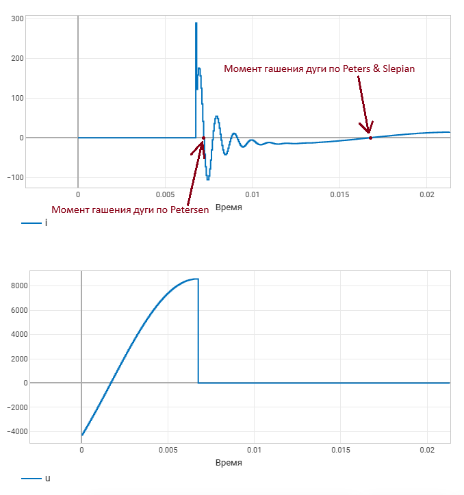
Petersen (high-frequency i == 0)zero at high frequency current fluctuations orPeters & Slepian (fundamental harmonic i == 0)at zero current of industrial frequency.
The unit can cause a short circuit (short circuit) both in time and in event. The arc is allowed as long as at least one trigger is active.
For a time-based short circuit, specify the short circuit activation time using the parameter Fault start time. The short circuit becomes inactive after the specified short circuit duration has expired.
For an event-based short circuit, specify the short circuit activation threshold using the parameter Fault threshold. The external control signal F controls the possibility of closing the arc circuit.
The figure below shows the equivalent electrical circuit of the unit.
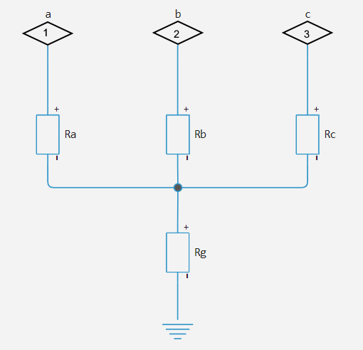
To determine the resistance in an equivalent circuit, use the corresponding equations from the table below.
| Short circuit mode | Value | Value | Value | Value | |
|---|---|---|---|---|---|
No / inactive |
|
|
|
Infinity/Open circuit |
|
Single-phase (to ground) |
- |
|
|
|
|
- |
|
|
|
|
|
- |
|
|
|
|
|
In the table:
|
|||||
Ports
Conserving
#
~
—
three-phase port
electricity
Details
Three-phase electrical port for connecting the unit to the circuit.
| Program usage name |
|
Entrance
# F — external damage trigger
+
scalar
Details
An external signal to trigger a short circuit (short circuit).
Dependencies
To use this port, check the box Enable external fault trigger.
| Типы данных |
|
| Support for complex numbers |
None |
Parameters
Main
Main group
#
Failure mode —
type of damage
None | Single-phase to ground (a-g) | Single-phase to ground (b-g) | Single-phase to ground (c-g)
Details
The type of short circuit for modeling. The following options are available:
-
None— KZ is missing; -
Single-phase to ground (a-g); -
Single-phase to ground (b-g); -
Single-phase to ground (c-g).
| Values |
|
| Default value |
|
| Program usage name |
|
| Evaluatable |
Yes |
# Faulted neutral-ground resistance, Ohm — neutral-ground resistance in case of damage
Details
The resistance between the neutral point and the ground when the short circuit is active is in ohms.
Dependencies
To use this parameter, set for the parameter Failure mode one of the following values:
-
Single-phase to ground (a-g); -
Single-phase to ground (b-g); -
Single-phase to ground (c-g).
| Default value |
|
| Program usage name |
|
| Evaluatable |
Yes |
# Faulted phase-neutral resistance, Ohm — phase-neutral resistance in case of damage
Details
The resistance between the phase and the neutral point with an active short circuit in ohms.
Dependencies
To use this parameter, set for the parameter Failure mode one of the following values:
-
Single-phase to ground (a-g); -
Single-phase to ground (b-g); -
Single-phase to ground (c-g).
| Default value |
|
| Program usage name |
|
| Evaluatable |
Yes |
# Unfaulted phase-neutral conductance, 1/Ohm — phase-neutral conductivity without damage
Details
The conductivity between the intact phase and the neutral point in Siemens.
| Default value |
|
| Program usage name |
|
| Evaluatable |
Yes |
External Trigger
# Enable external fault trigger — short circuit start by external signal
Details
Select this checkbox to enable the start of the short circuit on an external signal F.
| Default value |
|
| Program usage name |
|
| Evaluatable |
Yes |
# Fault threshold — the threshold value that causes a short circuit
Details
A short circuit occurs when an external signal crosses the threshold value in the direction specified in the short circuit condition (External fault trigger).
Dependencies
To use this option, check the box Enable external fault trigger.
| Default value |
|
| Program usage name |
|
| Evaluatable |
Yes |
#
External fault trigger —
the condition for the short circuit
Faulted if F ≥ Fault threshold | Faulted if F ≤ Fault threshold
Details
Select the condition that causes a short circuit:
-
Faulted if F ≥ Fault threshold— Short circuit occurs when the value of the external signal becomes greater than or equal to the value of the parameter Fault threshold; -
Faulted if F ≥ Fault threshold— Short circuit occurs when the value of the external signal becomes less than or equal to the value of the parameter Fault threshold.
Dependencies
To use this option, check the box Enable external fault trigger.
| Values |
|
| Default value |
|
| Program usage name |
|
| Evaluatable |
Yes |
# Fault resets when fault trigger reverts — short circuit termination when the trigger signal is restored
Details
Select this checkbox to terminate the short circuit at the moment when the value of the external signal F ceases to satisfy the condition External fault trigger.
Dependencies
To use this option, check the box Enable external fault trigger.
| Default value |
|
| Program usage name |
|
| Evaluatable |
Yes |
Temporal Trigger
# Enable temporal fault trigger — enable a temporary damage trigger
Details
Select this checkbox to enable the time limit start.
| Default value |
|
| Program usage name |
|
| Evaluatable |
Yes |
# Fault start time — damage start time
Details
The simulation time, in seconds, at which the block switches to the short circuit state.
Dependencies
To use this option, check the box Enable temporal fault trigger.
| Default value |
|
| Program usage name |
|
| Evaluatable |
Yes |
# Fault duration — duration of damage
Details
The duration of the short circuit simulation in seconds. The unit exits the short circuit state after the set time has elapsed.
Dependencies
To use this option, check the box Enable temporal fault trigger.
| Default value |
|
| Program usage name |
|
| Evaluatable |
Yes |
Arc Decay Control
# Allow arc decay when trigger is off — allow natural arc extinguishing after the trigger is removed
Details
Controls the behavior of an already burning arc after removing the general damage command.
With the value true removing the command prohibits new breakouts, but the existing arc continues to burn until it is extinguished according to the selected model. With the value false The arc is extinguished immediately after the damage command is removed.
| Default value |
|
| Program usage name |
|
| Evaluatable |
Yes |
First Fault Voltage Phase Control
# Enable voltage phase control — enable voltage phase control of the first fault
Details
Synchronizes the first ignition of the arc with the voltage phase at the fault site. The unit detects an upward voltage transition through zero and introduces a delay corresponding to the parameter Voltage phase shift, deg. At a given phase, the arc will light up only if all ignition conditions are met, including the ignition voltage.
| Default value |
|
| Program usage name |
|
| Evaluatable |
Yes |
# Fundamental frequency, Hz — the frequency of the fundamental harmonic
Details
Sets the mains frequency in Hz, used to convert the angular shift into a time delay to synchronize the first arc ignition with the voltage phase. The internal delay is calculated as Voltage phase shift, deg / (360 * Fundamental frequency, Hz).
Dependencies
To use this option, check the box Enable voltage phase control.
| Default value |
|
| Program usage name |
|
| Evaluatable |
Yes |
# Voltage phase shift, deg — phase shift of voltage
Details
Sets the angle in degrees from the detected voltage transition of the damaged phase up through zero to the resolution of the first arc ignition.
Dependencies
To use this option, check the box Enable voltage phase control.
| Default value |
|
| Program usage name |
|
| Evaluatable |
Yes |
Arc parameters
Arc Model
#
Arc model by —
the arc extinguishing model
Petersen (high-frequency i == 0) | Peters & Slepian (fundamental harmonic i == 0)
Details
Sets the theory of arc damping:
-
According to theory
Petersen (high-frequency i == 0)The arc is extinguished at the first transition through zero of the high-frequency arc current. -
According to theory
Peters & Slepian (fundamental harmonic i == 0)The arc is extinguished when the fundamental harmonic current passes through zero at a slower rate.
The figure below shows graphs of current in amperes and voltage in volts on the time axis in seconds when an intermittent arc is ignited.
| Values |
|
| Default value |
|
| Program usage name |
|
| Evaluatable |
Yes |
Time-Delay Parameters
#
Delay mode —
a method for determining the delay before arcing by Peters & Slepian
Time delay | Zero crossing
Details
Sets up as a model Peters & Slepian (fundamental harmonic i == 0) determines at which point the zero current can be extinguished by the arc:
-
Time delay— uses the set waiting time Waiting time after the ignition, s after ignition, and then allows the arc to be extinguished when zero is crossed. So, in the figure below, the parameter value is Waiting time after the ignition, s equally0.008c, after this time, the first crossing of zero current extinguishes the arc.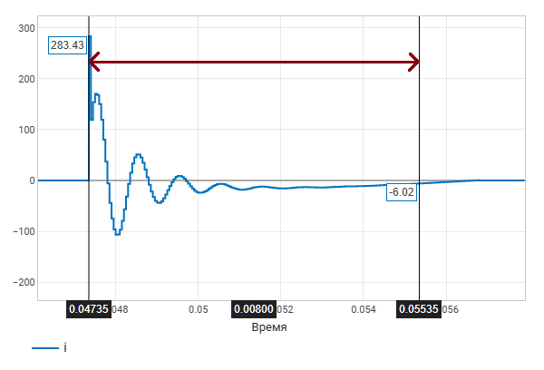
-
Zero crossing— waits for the filtered current of the main harmonic to pass through zero, and after it occurs, when the zero is crossed by the real current, it extinguishes the arc.
Dependencies
To use this parameter, set for the parameter Arc model by meaning Peters & Slepian (fundamental harmonic i == 0).
| Values |
|
| Default value |
|
| Program usage name |
|
| Evaluatable |
Yes |
# Waiting time after the ignition, s — waiting time after ignition
Details
Sets a fixed interval from the moment the arc is ignited to the formation of its extinguishing condition in seconds.
Dependencies
To use this parameter, set for the parameter Arc model by meaning Peters & Slepian (fundamental harmonic i == 0), and for the parameter Delay mode meaning Time delay.
| Default value |
|
| Program usage name |
|
| Evaluatable |
Yes |
# Natural frequency of low-pass filter, Hz — the natural frequency of the low-pass filter
Details
The natural frequency of the second-order low-pass filter in Hz, applied to the fault current to isolate the fundamental harmonic.
Dependencies
To use this parameter, set for the parameter Arc model by meaning Peters & Slepian (fundamental harmonic i == 0), and for the parameter Delay mode meaning Zero crossing.
| Default value |
|
| Program usage name |
|
| Evaluatable |
Yes |
Arc Ignition
#
Arc ignition voltage type —
arc ignition voltage type
Constant | Constant + pulse
Details
Sets the law for changing the ignition voltage. The arc can light up when the voltage module of the damaged phase is not less than the current ignition voltage.
-
Constant— uses constant ignition voltage. -
Constant + pulse— periodically pulsating ignition voltage between maximum and minimum levels.
| Values |
|
| Default value |
|
| Program usage name |
|
| Evaluatable |
Yes |
# Arc ignition voltage, V — constant arc ignition voltage
Details
Constant arc ignition voltage in volts.
Dependencies
To use this parameter, set for the parameter Arc ignition voltage type meaning Constant.
| Default value |
|
| Program usage name |
|
| Evaluatable |
Yes |
# Arc ignition voltage [max, min] — maximum and minimum ignition voltages
Details
Two-element vector [Vmax, Vmin] pulsating arc ignition voltage in volts. Ripple occurs at these two values.
Dependencies
To use this parameter, set for the parameter Arc ignition voltage type meaning Constant + pulse.
| Default value |
|
| Program usage name |
|
| Evaluatable |
Yes |
# Period, s — ignition voltage change period
Details
The period of the pulsating ignition voltage in seconds.
Dependencies
To use this parameter, set for the parameter Arc ignition voltage type meaning Constant + pulse.
| Default value |
|
| Program usage name |
|
| Evaluatable |
Yes |
# Pulse width, % of period — pulse width
Details
Pulse width of the pulsating ignition voltage as a percentage of the pulse period.
Dependencies
To use this parameter, set for the parameter Arc ignition voltage type meaning Constant + pulse.
| Default value |
|
| Program usage name |
|
| Evaluatable |
Yes |
# Phase delays, s — pulse threshold delay
Details
The delay before the generation of the first pulse of the pulsating ignition voltage in seconds.
Dependencies
To use this parameter, set for the parameter Arc ignition voltage type meaning Constant + pulse.
| Default value |
|
| Program usage name |
|
| Evaluatable |
Yes |
Arc Limitations
# Enable ignition number limit — limit the number of ignitions
Details
Enables the limit on the number of arc ignitions.
| Default value |
|
| Program usage name |
|
| Evaluatable |
Yes |
# Number of ignitions N — maximum number of ignitions
Details
The limit of the number of arc ignitions.
Dependencies
To use this option, check the box Enable ignition number limit.
| Default value |
|
| Program usage name |
|
| Evaluatable |
Yes |
# Enable time delay — enable pauses between ignitions
Details
Enables additional time pauses between successive arc ignitions.
Dependencies
To use this option, check the box Enable ignition number limit.
| Default value |
|
| Program usage name |
|
| Evaluatable |
Yes |
# Time delays between ignitions [t[1] .. t[N-1]], s — delays between ignitions
Details
Sets the vector of delays between successive ignitions in seconds. Element t[1] — this is the pause time between the ignition of the first arc and the permission to ignite the second, t[2] — between the second and the third, and so on. For N set the ignition settings N − 1 values. If the pause vector is longer N − 1, then only the first ones are executed N − 1 pauses. If the pause vector is shorter N − 1, then the rest of the ignition is performed without pauses.
Dependencies
To use this option, check the boxes Enable ignition number limit and Enable time delay.
| Default value |
|
| Program usage name |
|
| Evaluatable |
Yes |