EngeeDSP.Channelizer
A set of polyphase filters for FFT analysis.
| Library |
|
Description
System object EngeeDSP.Channelizer divides the broadband input signal into several narrow subbands using a set of filters based on the fast Fourier transform (FFT). The filter set uses a prototype low-pass filter and is implemented using a polyphase structure. The filter coefficients can be set directly or through the design parameters.
To split a broadband signal into several narrow sub-bands, follow these steps:
-
Create an object EngeeDSP.Channelizer and set its properties.
-
Call the object with arguments as if it were a function.
To learn more about how to work with system objects, see Engee System Objects.
Syntax
Creation
-
channelizer = EngeeDSP.Channelizer()— creates a system object of a set of polyphase filters for FFT analysis, which divides the broadband input signal into several narrowband output signals. This object implements the reverse operation with respect to the system object. EngeeDSP.ChannelSynthesizer. -
channelizer = EngeeDSP.Channelizer(M)— creates a set of polyphase filters for FFT analysis in -the range where the value NumFrequencyBands is set to .Example:
channelizer = EngeeDSP.Channelizer(16) -
channelizer = EngeeDSP.Channelizer(M,D)— creates a set of polyphase filters for FFT analysis in -the range that has for the property DecimationFactor value set .Example:
channelizer = EngeeDSP.Channelizer(16, 8) -
channelizer = EngeeDSP.Channelizer(Name=Value)— creates a system object of a set of polyphase filters for FFT analysis with specified properties in the form of a pairName=Value, whereName— the name of the property, andValue— the appropriate value. You can specify multiple pairs «name-value» the order of the pairs does not matter. Unspecified properties retain their default values.Example:
# создание системного объекта с коэффициентом децимации 4
channelizer = EngeeDSP.Channelizer(DecimationFactor = 4)
Arguments
Input arguments
# input — input data
+
vector | the matrix
Details
Input data set as a length vector or as a matrix of size on , where .
In most cases, the number of rows is The input data can be arbitrary and does not have to be a multiple of the number of frequency bands. See this table for details.
| The input signal | When starting an object in Engee | When generating the code |
|---|---|---|
Fixed size |
The object supports an arbitrary input frame length |
The object supports an arbitrary input frame length if, when generating the code for the property AllowArbitraryInputLength, the value is set |
Variable size |
The object supports an arbitrary input frame length |
The object supports an arbitrary input frame length |
Variable-size signals change the length of the frame after the object is locked, while fixed-size signals remain constant. If the object does not support an arbitrary frame length, the input frame length must be a multiple of the number of frequency bands.
| Типы данных |
|
| Support for complex numbers |
Yes |
Output arguments
# channOut is the output signal of the channel converter
+
the matrix | three-dimensional array
Details
The output signal of the channel converter, returned as a matrix or three-dimensional array.
If the input signal is a vector of length , then the size of the output signal is limited by the value on , where — the number of frequency bands. Each narrowband signal forms a column at the output.
If the input signal has more than one channel, then it has the size on , where , then the size of the output signal is limited by the value on on .
| Типы данных |
|
| Support for complex numbers |
Yes |
Features
# LowpassCoefficients — coefficients of the low-pass filter prototype
Details
The coefficients of the low-pass filter prototype, set as a string vector. The default vector of coefficients is obtained using the function rcosdesign(0.25, 6, 8, "sqrt"). There must be at least one coefficient for each frequency band. If the length of the low-pass filter is less than the number of frequency bands, the object adds zeros to the coefficients.
If complex coefficients are set, the facility will develop a prototype filter centered at a non-zero frequency, also known as a bandpass filter. The modulated versions of the bandpass filter prototype are displayed relative to the filter prototype and cover the frequency range .
Dependencies
To use this property, set the Specification value "Coefficients".
#
AllowArbitraryInputLength —
allow arbitrary input frame length in the generated code
Logical
Details
Allow arbitrary frame length for fixed-size input signals in the generated code by specifying the value true or false.
When specifying:
-
true— the length of the input frame does not have to be a multiple of the decimation factor. The output of the object in the generated code is an array of variable size. -
false— the length of the input frame must be a multiple of the decimation factor.
When specifying variable-size signals, the length of the input frame can be arbitrary, and the object ignores this property in the generated code. When running this object in Engee The object supports an arbitrary input frame length for signals of fixed and variable size, and this property does not affect the behavior of the object.
# DecimationFactor — decimation coefficient
Details
Decimation coefficient , set to one of the following values:
-
"Number of frequency bands"— when the value of the property NumFrequencyBands changes, the decimation coefficient changes automatically. -
A positive integer less than or equal to the number of frequency bands .
If the decimation coefficient is is equal to the number of frequency bands , that relation equally 1, and the channel converter is called a channel converter with maximum decimation.
If the relation is more 1 The sampling frequency of the output signal differs from the pitch of the channels, and the channel converter is called a channel converter without maximum decimation. If the ratio is an integer, the channel converter is called an integer oversampled channel converter. If the ratio is not an integer, for example 4/3 A channel converter is called a channel converter with rational oversampling. For more information, see Algorithms.
#
NumFrequencyBands —
number of frequency bands
Real number
Details
Number of frequency bands , into which the object divides the input broadband signal, set as a positive integer greater than 1. This property corresponds to the number of polyphase branches and the length of the FFT used in the filter set.
#
NumTapsPerBand —
number of filter coefficients per frequency band
Real number
Details
The number of filter coefficients used by each polyphase branch, set as a positive integer. The number of polyphase branches corresponds to the number of frequency bands. The total number of filter coefficients for the low-pass filter prototype is defined as NumFrequencyBands NumTapsPerBand. With a given attenuation in the delay band, increasing the number of taps per band narrows the filter transition width. As a result, the useful bandwidth for each frequency band increases due to increased computing costs.
Dependencies
To use this property, set the Specification value "Number of taps per band and stopband attenuation".
#
Specification —
design parameters or filter coefficients
String
Details
Filter design parameters or filter coefficients set using one of the following methods:
-
"Number of taps per band and stopband attenuation"— the filter design parameters are set using the properties NumTapsPerBand and StopbandAttenuation. -
"Coefficients"— the filter coefficients are set directly using the LowpassCoefficients.
#
StopbandAttenuation —
attenuation in the delay band
Real number
Details
Attenuation in the delay band of a low-pass filter, set as a positive real scalar in dB. This value controls the maximum number of overlapping spectra from one frequency band to another. As the attenuation in the delay band increases, the ripples in the passband decrease. With a given attenuation in the delay band, increasing the number of taps per band narrows the filter transition width. As a result, the useful bandwidth for each frequency band increases due to increased computing costs.
Dependencies
To use this property, set the Specification value "Number of taps per band and stopband attenuation".
Additional Info
A set of filters for analysis
Details
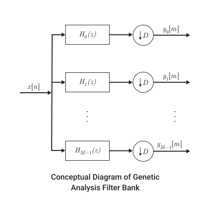
A standard set of filters for analysis consists of a series of parallel bandpass filters that separate the input broadband signal. on a number of narrow sub-bands. Each bandpass filter stores a different part of the input signal. After reducing the bandwidth by one of the bandpass filters, the signal is sampled at a lower sampling rate corresponding to the new bandwidth.
Low-pass filter prototype
Details
To effectively implement a set of filters for analysis, the channel converter uses a prototype low-pass filter.
The prototype low-pass filter has a pulse response , normalized two-way bandwidth and the cutoff frequency . — the number of frequency bands, that is, the branches of the filter set for analysis. This value corresponds to the length of the FFT used by the filter set. it can be large, on the order of 2048 or more. The attenuation in the delay band determines the minimum level of interference (contour distortion) from one frequency band to another. The ripples in the bandwidth must be small so that the input signal is not distorted in the bandwidth.
The prototype of the low-pass filter corresponds to in the filter set. The first branch of the filter set contains , followed by a decimator. The others the branches contain filters, which are modulated versions of the prototype filter. The modulation coefficient is determined by the following equation:
Using a low-pass filter prototype
Details
The transfer function of the modulated The th bandpass filter is given by the formula
This figure shows the frequency response filters.
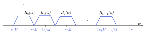
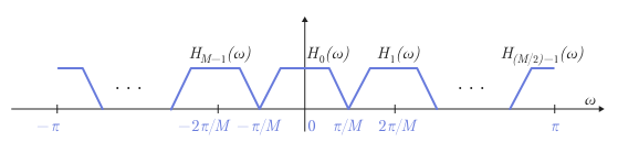
To obtain the frequency response of the filter , where , it is necessary to evenly shift the frequency response of the prototype filter by a multiple of . Each subband filter , where , is derived from the filter prototype.
Below is an equivalent representation of the frequency response diagram with , varying in the range of .
Shift of narrow sub-bands to the main frequency band
Details
Frequency components of the input signal are converted to a frequency band by multiplication for complex exponents:
The resulting signals pass through low-pass filters . The output signal of the low-pass filter has a relatively narrow bandwidth. The frequency of the signal is lowered in accordance with the new bandwidth. The decimation coefficient is selected , where — the number of branches of the filter set for analysis. If A channel converter is called a channel converter with oversampling or without maximum decimation.
The figure shows a set of filters for analysis using a prototype low-pass filter.
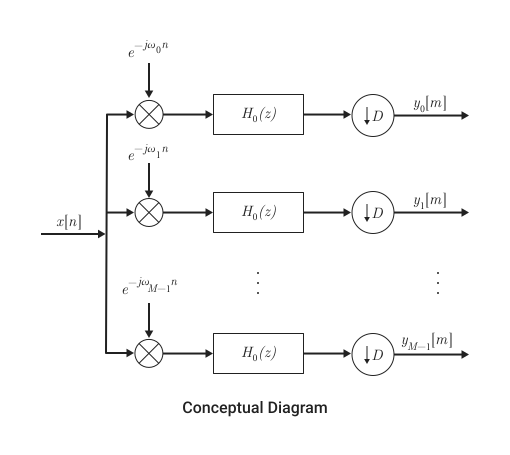
— signals of narrow sub-bands converted to the main frequency band.
Algorithms
Implementation using a polyphase structure
Details
A set of filters for analysis can be effectively implemented using a polyphase structure. For more information about the set of filters for analysis, see A set of filters for analysis.
To obtain a polyphase structure, let’s start with the transfer function of the prototype low-pass filter.:
where — the length of the filter prototype.
This equation can be reformulated as follows:
where — the number of polyphase components.
This equation can be written as follows:
where — polyphase components of the low-pass filter prototype .
The rest of the filters in the filter set , where , are modulated versions of this prototype filter.
The transfer function The th modulated bandpass filter can be written as .
Replacing on and ,
In the polyphase form, the equation looks like this:
For everyone channels in the filter set transfer function It is set as follows:
Channel converter with maximum decimation
Details
When A channel converter is called a channel converter with maximum decimation or a channel converter with critical sampling.
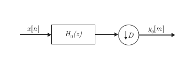
Here is a multi-rate remarkable identity for frequency reduction (decimation), suggesting that .

For example, consider the first branch of a set of filters containing a low-pass filter.
Replace its polyphase representation.
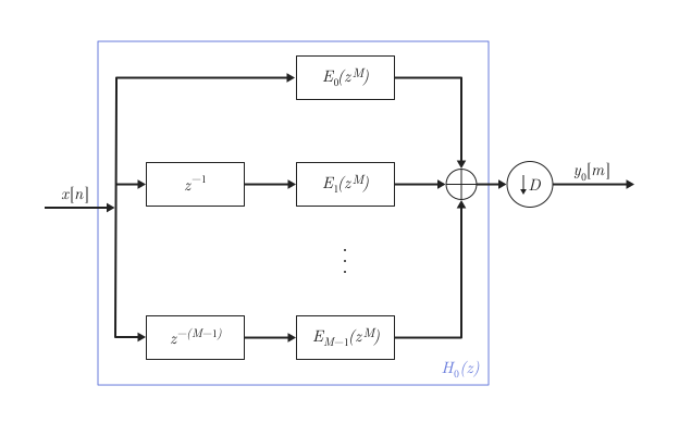
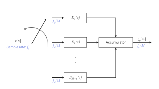
After applying the remarkable decimation identity, it is possible to replace the delays and decimation coefficient with a switching device. The switching device starts moving from the first branch 0 and moves counterclockwise, as shown in the following diagram. The output battery receives processed input samples from each branch of the polyphase structure and accumulates these processed samples until the switching device moves to branch 0. When the switching device moves to branch 0, the battery outputs the accumulated value.
For everyone channels in the filter set transfer function It is set as follows:
The matrix on the left is the inverse discrete Fourier transform (ODFT) matrix. Using the ODPF matrix, the effective implementation of a set of filters based on a prototype low-pass filter is as follows.
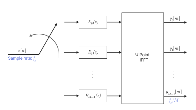
When the channel converter receives the first input sample, the switching device feeds this input to branch 0, and the channel converter calculates the first set of output values. As new input samples arrive, the switching device moves counterclockwise through the branches. , and up to branch 0, applying one count to each branch. When the switching device reaches branch 0, the channel converter outputs the following set of output values. This process continues as the data becomes available. Each time the switching device reaches the first branch 0, the channel converter outputs . Each branch of the channel converter actually outputs one sample for each received counts. Therefore, the sampling frequency at the output of the channel converter is .
If you use -point FFT, the implementation will look like this.
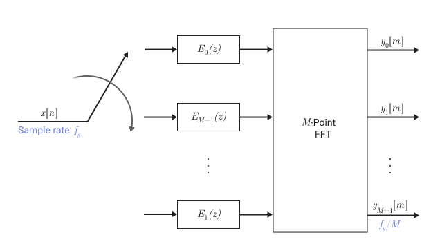
When the switching device transmits the first sample to branch 0, the channel converter calculates the first set of output values. As new data arrives, the switching device moves clockwise to the branches , and so on to branch 1, passing one count to each branch. When the switching device reaches branch 0, the channel converter outputs the following set of output values. This process continues as new data becomes available.
Channel converter without maximum decimation or channel converter with oversampling
Details
When A channel converter is called a channel converter without maximizing the sampling rate or a channel converter with oversampling. In this configuration, the sampling frequency of the output signal differs from the step between the channels. Channel converters provide greater design freedom without maximizing the sampling rate, but at the cost of increased computational costs.
If the relation is is equal to an integer greater than 1 and less or equal , a channel converter is called a channel converter with integer oversampling. If the relation is If it is not an integer, then the channel converter is called a channel converter with rational oversampling.
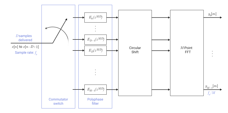
In this configuration, when the first input sample arrives, the switching device feeds this input to branch 0, and the channel converter calculates the first set of output values. As new input samples arrive, the switching device moves counterclockwise through the branches , and up to branch 0, feeding one count at a time to each branch. When the switching device switches to branch 0, the channel converter outputs the following set of output values. This process continues as the data becomes available. Each time the switching device switches to the first branch 0, the channel converter outputs .
As new data arrives and these samples are sent by the switching device to the first addresses, the formal contents of these addresses are shifted to the following set addresses, and this data shifting process continues each time a new set of input counts.
For each The channel converter outputs input samples supplied to the polyphase structure. counts, . This process increases the sampling rate of the output data with in the case of a channel converter with maximum decimation up to in the case of a channel converter without maximum decimation.
For more information, see [2].
After each sequence of data -points are received on a divided by -stepwise polyphase filter, output signals -steps are calculated and processed for submission to -point FFT. Shifting the data through the filter introduces a frequency-dependent phase shift. To correct this phase shift and superimpose all bands on a constant component, after the polyphase filters and before -a cyclic shift buffer is inserted with a dot FFT.
With a switchboard followed by -a stepwise polyphase filter, a cyclic shift buffer and a DFT matrix, an effective implementation of a set of filters based on a prototype low-pass filter is as follows.
Literature
-
Harris, Fredric J, Multirate Signal Processing for Communication Systems, Prentice Hall PTR, 2004.
-
Harris, F.J., Chris Dick, and Michael Rice. «Digital Receivers and Transmitters Using Polyphase Filter Banks for Wireless Communications.» IEEE® Transactions on Microwave Theory and Techniques. 51, no. 4 (2003).