Backlash
A model of the behavior of a system with backlash.
blockType: Backlash
|
Path in the library: |

Description
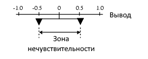
Block Backlash implements a system in which a change in the signal at the Input causes the same change at the output, except when the sign of the change in the input signal changes (begins to decrease after increasing or vice versa). When this happens, at the first moment the change in the input signal does not affect the output. The amount of backlash in the system is called the dead zone and is set by the parameter Deadband width. The dead zone is symmetrical with respect to the value of the output signal. The figure below shows the initial state with the width of the dead zone by default equal to 1, and the initial value of the output signal equal to 0.
A backlash system can be in one of three modes.
| Mode | Input | Output |
|---|---|---|
Disabled |
Inside the zone of insensitivity. |
Remains constant. |
Positive direction |
Out of the zone of insensitivity and increases. |
Equal to the value at the Input minus half the width of the dead zone. |
Negative direction |
Out of the zone of insensitivity and decreases. |
Equal to the Input value plus half the width of the dead zone. |
Parameter Initial output sets the initial center of the dead zone.
This table shows the output values under the following initial conditions: Deadband width = 2 and Initial output = 5.
| Output value | Status |
|---|---|
5 |
4 ⇐ Input ⇐ 6 |
Input + 1 |
output < 4 |
Input − 1 |
output > 6 |
For example, you can use the block Backlash to simulate the engagement of two gears mounted on the input and output shafts of the simplest gearbox: the input shaft rotates the second through a gear transmission. The gap between the gear teeth creates backlash. The width of this gap determines the value of the parameter Deadband width. If the system is initially stationary, then the value of the output signal is set by the parameter Initial output.
The figures below illustrate the operation of the unit, provided that the initial value of the output signal is within the dead zone and the system starts from a stationary state.
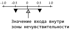
When the Input increases and reaches the end of the dead zone, it turns on the output. The output remains at the same level.
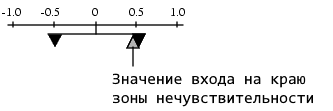
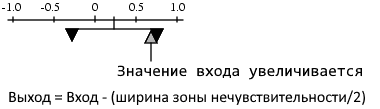
After the Input interacts with the output, the output changes by the same amount as the Input.
If the Input changes direction, it disconnects from the output. The output remains constant until the Input reaches the end of the dead zone and fires again.
Ports
Input
#
IN_1
—
Input signal
scalar | vector
Details
The input signal for the backlash algorithm. The value of this signal is either in the dead zone or includes an output in the positive or negative direction.
| Data types |
|
| Complex numbers support |
Yes |
Output
#
OUT_1
—
Output signal
scalar | vector
Details
The output signal is after applying the backlash algorithm to the input signal. When the Input is in the dead zone, the output remains unchanged. If the Input is connected to the output, then the output changes to the same extent as the Input.
| Data types |
|
| Complex numbers support |
Yes |
Parameters
Main
#
Deadband width —
the width of the dead zone
Scalar / array of real numbers
Details
Sets the size of the dead zone centered relative to the output value. When the input signal is inside the dead zone, a change in the input does not cause a change in the output. When the input signal is outside the dead zone, the output signal changes as much as the input signal.
| Default value |
|
| Program usage name |
|
| Tunable |
Yes |
| Evaluatable |
Yes |
#
Initial output —
initial output value
Scalar / array of real numbers
Details
Sets the initial center of the dead zone. If the initial value of the input signal is in the dead zone, then the output value is Initial output. If the initial input value is outside the dead zone, the output value is equal to the initial output plus or minus half the width of the dead zone.
| Default value |
|
| Program usage name |
|
| Tunable |
Yes |
| Evaluatable |
Yes |