PWM
Generates an ideal signal with pulse width modulation in accordance with the input signal of the well.
blockType: PWM
|
Path in the library: |

Description
Block PWM generates an ideal signal with pulse width modulation.
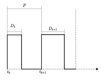
Pulse width modulation (PWM) is a method of encoding an analog signal using square pulses usage. The principle of PWM is to change the pulse duration at a constant pulse frequency. The ratio of pulse duration to period is called duty cycle. The relationship between the modulated signal and the duty cycle is described as follows:
Where and — the upper and lower limits of the output signal, respectively.
For the block PWM the duty cycle lies in the range [0,1]. The ideal PWM signal is proportional to the duty cycle .
Ports
Input
#
IN_1
—
working cycle
scalar
Details
Relative pulse duration in the form of a scalar in the range [0,1].
| Data types |
|
| Complex numbers support |
Yes |
Output
#
OUT_1
—
The output signal
scalar | vector | the matrix
Details
A PWM signal with an operating cycle equal to the value of the input signal.
| Data types |
|
| Complex numbers support |
Yes |
Parameters
Main
#
Period —
pulse period
Scalar / array of real numbers
Details
The time between the rising edges of successive pulses of the output signal. A small value corresponds to a high-frequency pulse.
| Default value |
|
| Program usage name |
|
| Tunable |
Yes |
| Evaluatable |
Yes |
#
Disallow zero duty cycle —
avoid algebraic loops
Logical
Details
Enable this option to break the algebraic loops containing the block. PWM.
Enabling this parameter causes the signal value to become equal to 0 or lower, which will cause an input error.
|
| Default value |
|
| Program usage name |
|
| Tunable |
No |
| Evaluatable |
No |
#
Sample Time —
the interval between the calculation steps
SampleTime (real number / vector of two real numbers)
Details
Specify the interval between the calculation steps as a non-negative number.
Meaning -1 for the parameter Sample Time leads to an error.
|
| Default value |
|
| Program usage name |
|
| Tunable |
No |
| Evaluatable |
Yes |