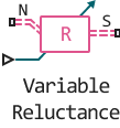
Variable Reluctance
Variable magnetic resistance.
blockType: AcausalFoundation.Magnetic.Elements.VariableReluctance
|
Path in the library: |
Description
Block Variable Reluctance It is an alternating magnetic resistance, that is, a component that resists magnetic flux. The ratio of the magnetomotive force (MDS) on the component to the resulting flow flowing through the component is defined as resistance and depends on the value of the input signal.
The block is based on the following equations:
,
,
Where:
-
— magnetomotive force (MDS) on the component.
-
— flow through magnetic ports.
-
— magnetic resistance.
-
— The value on the input port.
-
— magnetic constant.
-
— relative magnetic permeability of the material.
-
— the cross-sectional area of the simulated element.
N and S connections are magnetic ports. MDS through resistance is defined by the expression , and the sign of the magnetic flux is positive when flowing through the device from N to S.
Input
N — north terminal
magnetic
The magnetic port corresponding to the north terminal of the unit.
S — south terminal
magnetic
The magnetic port corresponding to the southern terminal of the unit.
Port_1 — input signal
scalar
The input port that sets the value of the length of the air gap or the thickness of the section.
Parameters
Minimum length of thickness X>=0, m — minimum clearance X>=0
0 (by default)
The minimum value of the length of the air gap or the thickness of the section. If the input signal falls below this level (for example, it becomes negative), the minimum value is used. The parameter value must be non-negative.
Cross-sectional area, m^2 — cross-sectional area of
0.01 m2 (by default)
The cross-sectional area of the simulated element.
Relative permeability of material — relative permeability of material
1 (by default)
Relative magnetic permeability of the material.
Initial value of flux, Wb — initial value of the flow
0 (by default)
The initial value of the stream.
Initial value of MMF, A — initial value of MMF
0 (by default)
The initial value of the MDS.
