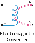
Electromagnetic Converter
The interface between the electrical and magnetic networks.
blockType: AcausalFoundation.Magnetic.Elements.ElectromagneticConverter
|
Path in the library: |
Description
The Electromagnetic Converter unit provides an interface between electrical and magnetic networks.
The block is based on the following equations:
,
,
Where:
-
- is the magnetomotive force (MDF) at the magnetic ports.
-
- flux through the magnetic ports.
-
- current through the electrical ports.
-
- voltage across the electrical ports.
-
- number of winding turns.
-
- modelling time.
Connections N and S are magnetic ports, and connections + and - are electrical ports. If a positive electric current flows from port + to port - , the resulting MDS is positive, acting through the magnetic ports N to S. The positive rate of change of flux flowing from N to S results in a negative induced potential difference at ports + and - .
Ports
N - north terminal
`magnetism
Magnetic port corresponding to the north terminal of the unit.
S is the south terminal
magnetism
Magnetic port corresponding to the south terminal of the unit.
+ - positive
electricity
The electrical port corresponding to the positive terminal of the unit.
- - negative
electricity
The electrical port corresponding to the negative terminal of the unit.
Parameters
Number of winding turns - number of winding turns
`1 (By default)
Number of winding turns.
Initial value of voltage, V - initial value of voltage
0 (By default)
Initial value of voltage.
Initial value of current, A - initial value of current
0 (By default)
Initial value of current.
Initial value of flux, Wb - initial value of flux
0 (By default).
Initial value of flux.
Initial value of MMF, A - initial value of MMF
0 (By default).
Initial value of MMF.
