An extended example of formal verification in Engee
This example shows how to verify a model containing several interconnected Chart blocks, as well as how to verify complex functional dependencies and conflicting requirements.
Model WM.engee is a compound of three blocks Chart: LEFT_DU, RIGHT_DU and CURSOR_LOGIC (decompressed subsystems for compactness of images):
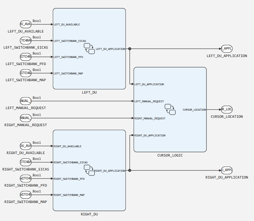
It is assumed that the three inputs [LEFT_SWITCHBANK_EICAS, LEFT_SWITCHBANK_PFD, LEFT_SWITCHBANK_MAP] and [RIGHT_SWITCHBANK_EICAS, RIGHT_SWITCHBANK_PFD, RIGHT_SWITCHBANK_MAP] receive data from three-position switches, i.e. in each triple at any given time, only one of the three inputs can have a true signal.
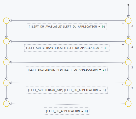
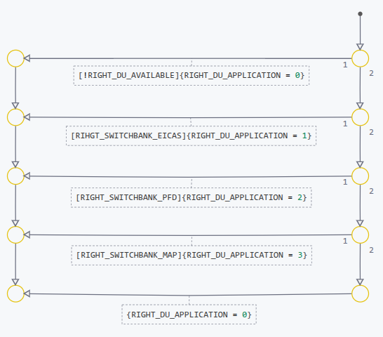
The LEFT_DU (left) and RIGHT_DU (right) blocks are transition diagrams:
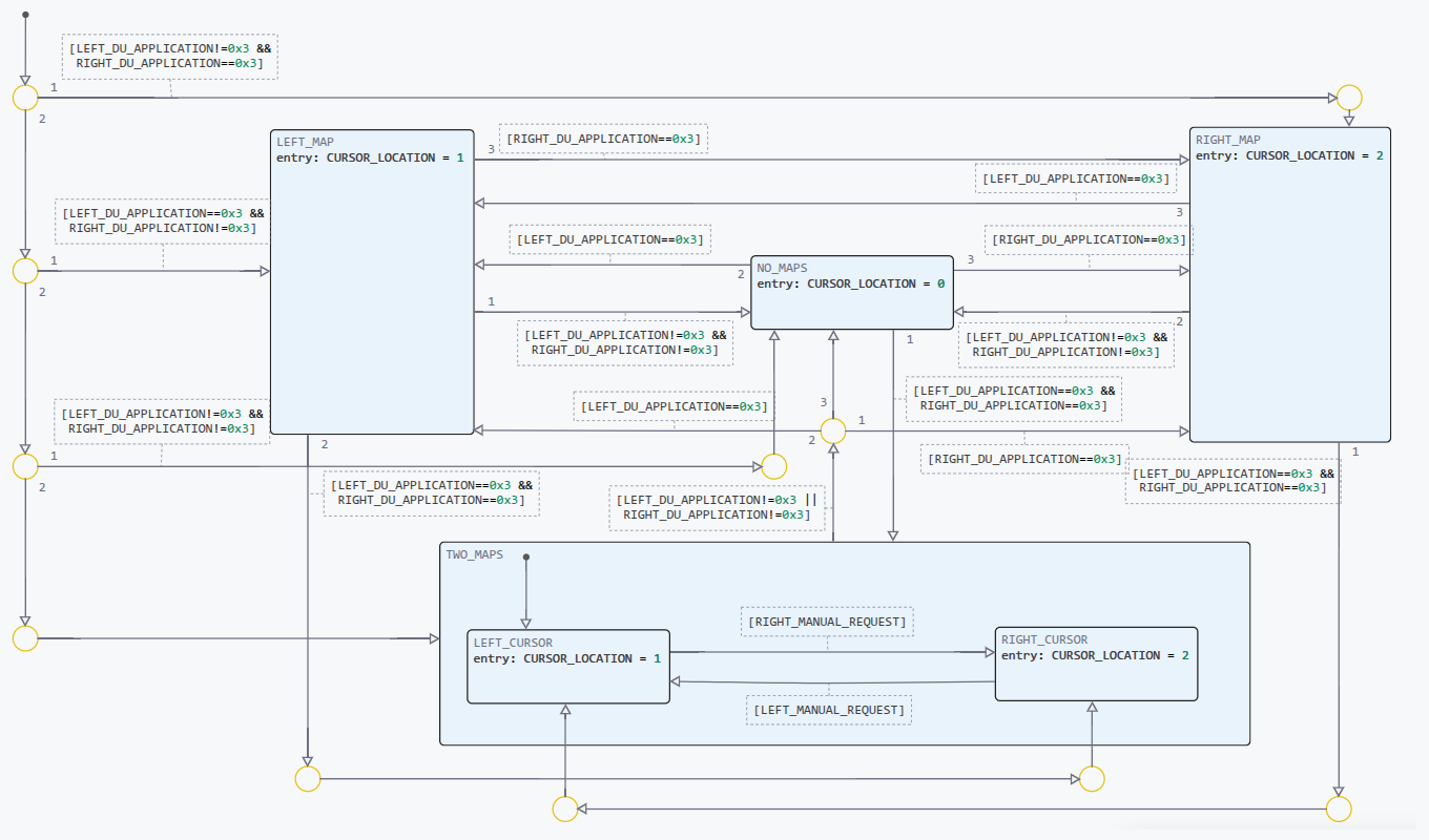
The CURSOR_LOGIC block:
The model specification consists of 9 requirements.:
-
R1: If the display (DU) is ready for operation, then it should display some application;
-
R2: If the display (DU) is not ready for operation, then it should not attempt to display any of the applications.;
-
R3: The cursor should not be displayed on the display (DU), which is not ready for operation;
-
R4: The cursor should not be displayed on the display (DU), which displays an application other than the MAP application (Aeronautical charts and diagrams display system);
-
R5: When the MAP application is selected for display (DU), then the cursor should be moved to this display (DU).;
-
R6: When the button for selecting the display of the engine operating parameters and crew warning system (SELECT_EICAS) is pressed, the EICAS application should be displayed on the display;
-
R7: When the main flight display selection button (SELECT_PFD) is pressed, the PFD application should be displayed on the display;
-
R8: When the button for selecting the display of the aeronautical charts and diagrams display system (SELECT_MAP) is pressed, the MAP application should be displayed on the display.;
-
R9: Each variable of the DU_APPLICATION application displayed must be assigned a value from
0before3.
Due to the fact that the blocks Inport (CE) in our case, zero values are always generated, simulation of the model is uninformative, and verification is impossible, so let’s change the Promela model in such a way that instead of Inport blocks, the model uses random logic generators, and, as mentioned above, the signals inside the triples [LEFT_SWITCHBANK_EICAS, LEFT_SWITCHBANK_PFD, LEFT_SWITCHBANK_MAP] and [RIGHT_SWITCHBANK_EICAS, RIGHT_SWITCHBANK_PFD, RIGHT_SWITCHBANK_MAP] are interconnected and simulate three-position switches.
Typically, a random logic signal in Promela is modeled using non-deterministic conditional operator:
if
:: s = true;
:: s = false;
fi
or the operator select (for more information, see select):
select(s: false .. true);A three-position random switch can be modeled as
if
:: s1 = true; s2 = false; s3 = false;
:: s1 = false; s2 = true; s3 = false;
:: s1 = false; s2 = false; s3 = true;
fi
Therefore, since the inputs are defined in the Promela model as
typedef Ext_WM_U {
    bool RIGHT_SWITCHBANK_MAP               /* /RIGHT_SWITCHBANK_MAP */
    bool LEFT_SWITCHBANK_EICAS              /* /LEFT_SWITCHBANK_EICAS */
    bool LEFT_DU_AVAILABLE                  /* /LEFT_DU_AVAILABLE */
    bool LEFT_MANUAL_REQUEST                /* /LEFT_MANUAL_REQUEST */
    bool RIGHT_SWITCHBANK_PFD               /* /RIGHT_SWITCHBANK_PFD */
    bool RIGHT_DU_AVAILABLE                 /* /RIGHT_DU_AVAILABLE */
    bool LEFT_SWITCHBANK_PFD                /* /LEFT_SWITCHBANK_PFD */
    bool RIGHT_SWITCHBANK_EICAS             /* /RIGHT_SWITCHBANK_EICAS */
    bool RIGHT_MANUAL_REQUEST               /* /RIGHT_MANUAL_REQUEST */
    bool LEFT_SWITCHBANK_MAP                /* /LEFT_SWITCHBANK_MAP */
};

/* External inputs */
Ext_WM_U WM_U;
Let’s add it to the beginning of the process fsm, which acts as a step function, a section for generating random data entering the left and right inputs:
active proctype fsm() {
do
:: true -> atomic {
    if
    :: WM_U.LEFT_DU_AVAILABLE = true
    :: WM_U.LEFT_DU_AVAILABLE = false
    fi
    if
    :: WM_U.LEFT_SWITCHBANK_EICAS = true; WM_U.LEFT_SWITCHBANK_PFD = false; WM_U.LEFT_SWITCHBANK_MAP = false;
    :: WM_U.LEFT_SWITCHBANK_EICAS = false; WM_U.LEFT_SWITCHBANK_PFD = true; WM_U.LEFT_SWITCHBANK_MAP = false;
    :: WM_U.LEFT_SWITCHBANK_EICAS = false; WM_U.LEFT_SWITCHBANK_PFD = false; WM_U.LEFT_SWITCHBANK_MAP = true;
    fi
    if
    :: WM_U.RIGHT_DU_AVAILABLE = true
    :: WM_U.RIGHT_DU_AVAILABLE = false
    fi
    if
    :: WM_U.RIGHT_SWITCHBANK_EICAS = true; WM_U.RIGHT_SWITCHBANK_PFD = false; WM_U.RIGHT_SWITCHBANK_MAP = false;
    :: WM_U.RIGHT_SWITCHBANK_EICAS = false; WM_U.RIGHT_SWITCHBANK_PFD = true; WM_U.RIGHT_SWITCHBANK_MAP = false;
    :: WM_U.RIGHT_SWITCHBANK_EICAS = false; WM_U.RIGHT_SWITCHBANK_PFD = false; WM_U.RIGHT_SWITCHBANK_MAP = true;
    fi
The model is now ready for verification.
Let’s shorten the names:
// Inputs:
#define LEFT_DU_AVAILABLE WM_U.LEFT_DU_AVAILABLE
#define LEFT_SWITCHBANK_EICAS WM_U.LEFT_SWITCHBANK_EICAS
#define LEFT_SWITCHBANK_MAP WM_U.LEFT_SWITCHBANK_MAP
#define LEFT_SWITCHBANK_PFD WM_U.LEFT_SWITCHBANK_PFD
#define RIGHT_DU_AVAILABLE WM_U.RIGHT_DU_AVAILABLE
#define RIGHT_SWITCHBANK_EICAS WM_U.RIGHT_SWITCHBANK_EICAS
#define RIGHT_SWITCHBANK_MAP WM_U.RIGHT_SWITCHBANK_MAP
#define RIGHT_SWITCHBANK_PFD WM_U.RIGHT_SWITCHBANK_PFD

// Outputs:
#define RIGHT_DU_APPLICATION WM_Y.RIGHT_DU_APPLICATION
#define LEFT_DU_APPLICATION WM_Y.LEFT_DU_APPLICATION
#define CURSOR_LOCATION WM_Y.CURSOR_LOCATION
Also, for clarity, we will define symbolic names for application numbers.:
#define BLANK 0
#define EICAS 1
#define PFD 2
#define MAP 3
We will create a formal specification for each informal requirement.
R1: If the display (DU) is ready for operation, then it should display some application.
For the first display:
ltl r1_1 { [] (LEFT_DU_AVAILABLE -> LEFT_DU_APPLICATION != BLANK) }For the second one:
ltl r1_2 { [] (RIGHT_DU_AVAILABLE -> RIGHT_DU_APPLICATION != BLANK) }R2: If the display (DU) is not ready for operation, then it should not attempt to display any of the applications.
ltl r2_1 { [] (!LEFT_DU_AVAILABLE -> LEFT_DU_APPLICATION == BLANK ) }
ltl r2_2 { [] (!RIGHT_DU_AVAILABLE -> RIGHT_DU_APPLICATION == BLANK ) }
R4: The cursor should not be displayed on the display (DU), which displays an application other than the MAP application (Aeronautical charts and Diagrams display system).
ltl r4_1 { [] (LEFT_DU_APPLICATION != MAP -> CURSOR_LOCATION != 1) }
ltl r4_2 { [] (RIGHT_DU_APPLICATION != MAP -> CURSOR_LOCATION != 2) }
R5: When the MAP application is selected for display (DU), then the cursor should be moved to this display (DU).
ltl r5_1 { [] (LEFT_DU_APPLICATION != MAP -> X (LEFT_DU_APPLICATION == MAP -> CURSOR_LOCATION == 1)) }
ltl r5_2 { [] (RIGHT_DU_APPLICATION != MAP -> X (RIGHT_DU_APPLICATION == MAP -> CURSOR_LOCATION == 2)) }
Requirement r5_2 is verified with an error (with a different implementation Engee-the error would have been caused by requirement r5_1).
It’s easy to see that the error is not in the model, but in the specifications themselves.:
-
It is known from the problem statement that the cursor can only be on one display at a time.;
-
After the MAP application has been selected, the cursor should move to the display where it is displayed.;
-
Nothing prevents you from selecting the MAP application on both displays at the same time.
This results in the uncertainty of the cursor position, which is inconsistent with the requirements — the requirements are mutually contradictory and need to be clarified.
All other requirements are verified successfully.
R6: When the button for selecting the display of the engine operating parameters and crew warning system (SELECT_EICAS) is pressed, the EICAS application should be displayed on the display.
ltl r6_1 { [] (LEFT_DU_AVAILABLE && LEFT_SWITCHBANK_EICAS -> LEFT_DU_APPLICATION == EICAS) }
ltl r6_2 { [] (RIGHT_DU_AVAILABLE && RIGHT_SWITCHBANK_EICAS -> RIGHT_DU_APPLICATION == EICAS) }
R7: When the main flight display selection button (SELECT_PFD) is pressed, the PFD application should be displayed on the display.
ltl r7_1 { [] (LEFT_DU_AVAILABLE && LEFT_SWITCHBANK_PFD -> LEFT_DU_APPLICATION == PFD) }
ltl r7_2 { [] (RIGHT_DU_AVAILABLE && RIGHT_SWITCHBANK_PFD -> RIGHT_DU_APPLICATION == PFD) }
R8: When the button for selecting the display of the aeronautical charts and diagrams display system (SELECT_MAP) is pressed, the MAP application should be displayed on the display.
ltl r8_1 { [] (LEFT_DU_AVAILABLE && LEFT_SWITCHBANK_MAP -> LEFT_DU_APPLICATION == MAP) }
ltl r8_2 { [] (RIGHT_DU_AVAILABLE && RIGHT_SWITCHBANK_MAP -> RIGHT_DU_APPLICATION == MAP) }
R9: Each variable of the DU_APPLICATION application displayed must be assigned a value from 0 before 3.
ltl r9_1 { [] (LEFT_DU_APPLICATION <= 3 && LEFT_DU_APPLICATION >= 0) }
ltl r9_2 { [] (RIGHT_DU_APPLICATION <= 3 && RIGHT_DU_APPLICATION >= 0) }
Verification results
As a result of verification, all specifications except r5_2 (and with a different implementation r5_1), are running successfully. The discovered violation is not related to a model error, but to a contradiction in the initial requirements, which underlines the need for a formal verification of specifications for consistency.