Verilog (HDL) code generation
In addition to C-code generation, Verilog code can also be generated from a limited set of blocks in Engee.
Verilog is a popular hardware description language (HDL) used for ASIC and FPGA design and testing. The generated code can be synthesised into a netlist that is used for ASIC photolithography or FPGA firmware creation.
The process of generating Verilog code is similar to generating C code.
-
In settings window
 , click the Code generation tab and select Verilog for the Target hardware option;
 -
Click Generate code
 in the upper left corner of the workspace;
 -
In file browser
 in the
 {model_name}_codefolder, a file with the .v extension will appear - the generated Verilog code.
You can also use the generate_code function, specifying Verilog as the target language.
Verilog code generator options
Supported data types:
-
Integer types of any width up to 128 bits, including non-standard sizes (not just degrees of two);
-
Sign types with fixed point and positive fractional length.
Also available:
-
Code generation from virtual subsystems;
-
Custom templates (see Code generation based on custom templates);
-
Verification of generated code (see ). [verification]).
Example
Consider the model from example, which is a PID controller. The data types used are fixed point numbers:
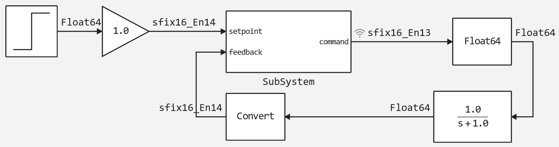
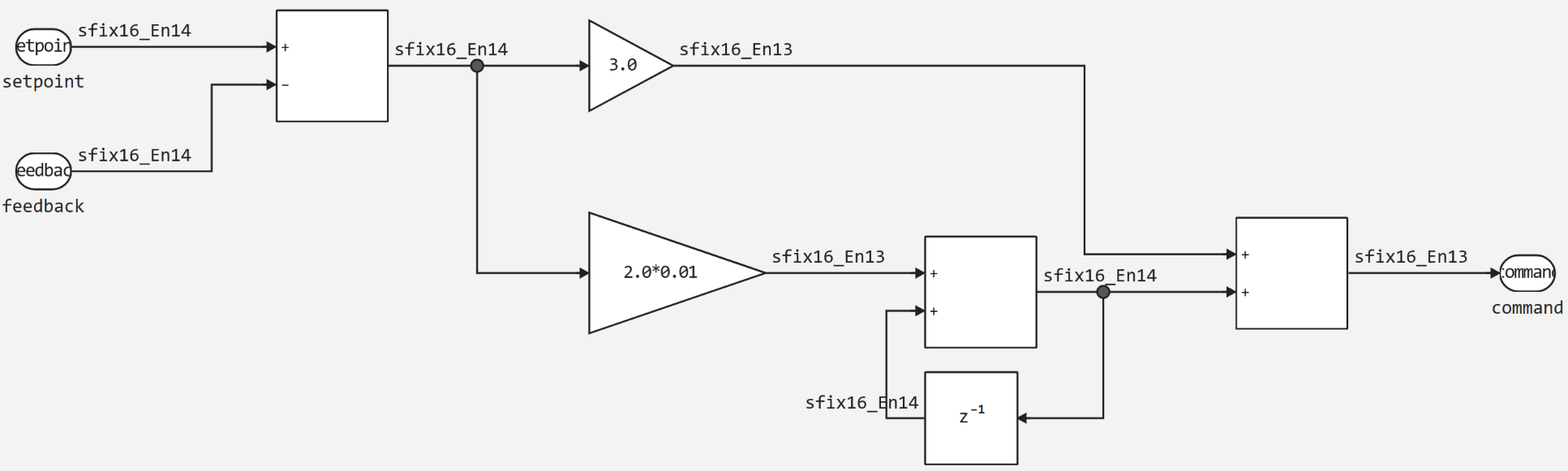
The basic algorithm is implemented in the subsystem (block Subsystem):
Since the algorithm is implemented in the subsystem, Verilog code will be generated from it. To do this, set Verilog as the target platform in settings window ![]() and execute the command in the terminal:
and execute the command in the terminal:
engee.generate_code("pid_fixed.engee", "pid_fixed_code", subsystem_name="SubSystem", target="verilog")Here:
-
pid_fixed.engee- model name; -
pid_fixed_code- folder where Verilog code will be generated; -
subsystem_name="SubSystem- indicates the subsystem from which the code will be generated; -
target="verilog- specifies the language for the code generator.
|
Instead of specifying the file name explicitly, you can also pass the current open model with |
After executing the command, the file pid_fixed.v will appear in file browser with the following Verilog code:
module pid_fixed_SubSystem(
  input         clock,
                reset,
  input  [15:0] io_setpoint,
                io_feedback,
  output [15:0] io_command
);

  reg  [15:0] UnitDelay_state;
  wire [15:0] _AddAccum_T = io_setpoint - io_feedback;
  wire [41:0] _Gain_2_new_T_3 = {{26{_AddAccum_T[15]}}, _AddAccum_T} * 42'h148000;
  wire [29:0] _Gain_new_T_1 = {{14{_AddAccum_T[15]}}, _AddAccum_T} * 30'h6000;
  wire [15:0] _Add_1Accum_T = {_Gain_2_new_T_3[41:27], 1'h0} + UnitDelay_state;
  always @(posedge clock) begin
    if (reset)
      UnitDelay_state <= 16'h0;
    else
      UnitDelay_state <= _Add_1Accum_T;
  end // always @(posedge)
  assign io_command = _Gain_new_T_1[29:14] + {_Add_1Accum_T[15], _Add_1Accum_T[15:1]};
endmodule
The generated code has the following features:
-
The
clockandresetsignals are always generated; -
Both sequential and combinatorial logic are used, but combinatorial loops are not supported;
-
resetis always synchronous and active-high.
[#verification]; == Verification
Verification involves creating a verification model with the C Function; block, whose simulation results should match the results of the original model with the same input data.
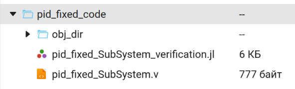
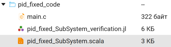
As with C code generation, you can enable the option "Generate C Function block" in the settings window on the "Code Generation" tab. In this case, in addition to the Verilog (.v) file, the folder with the generated Verilog code will contain:
-
.jl script;
-
The obj_dir folder containing the following auxiliary files:
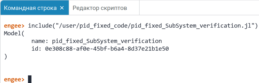
The file pid_fixed_Subsystem_verification.jl contains a script in the command control language. To get the verification model, you need to execute this file. You can do this in two ways:
-
Enter the
include("/path/to/file")command at command line :
:
-
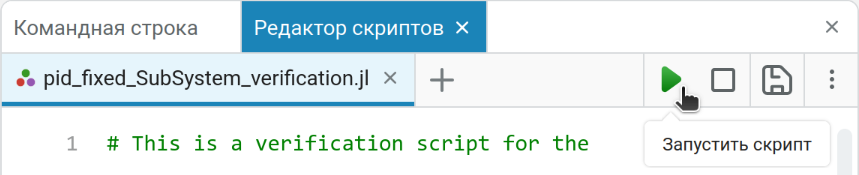
Click the "Run Script" button
 in the upper-right corner of script editor
  :
:
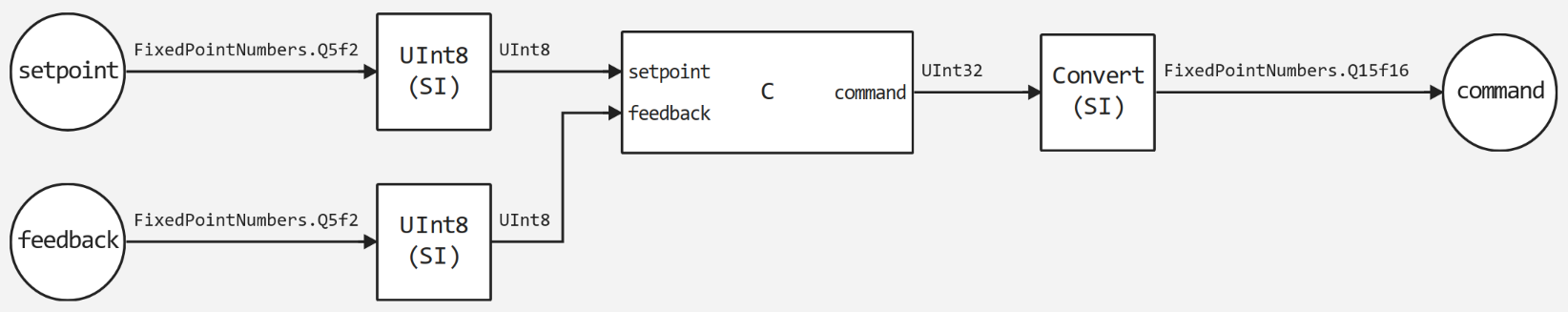
The script will result in a model {model_name}_verification.engee. It includes:
-
The input and output blocks of the source model (or subsystem);
-
The C Function block;
-
Auxiliary blocks for conversion of signal types (if the model uses fixed-point types).
Simplified, the C Function block contains the Verilog code generated from the source model. Thanks to this it is possible to:
-
Enable output recording or save simulation results in the workspace. Then compare the simulation results of the original model and the verification model on the same input data (they must match);
-
Build the verification model as a subsystem of the source model and compare the results.
|
Conventional general purpose processors cannot directly execute Verilog RTL code intended for synthesis. However, this is possible using emulators such as Verilator. This tool converts Verilog code into equivalent behavioural C++ code, which can be run to compare the results. The generated C++ code is packaged in a library containing an interface to control the simulation, and the auxiliary files are placed in the obj_dir folder (mentioned earlier). The C Function block in the verification model then uses this library to operate. |
How Verilog works internally

For advanced users, such as template developers for HDL code generation, it is important to understand the steps of Verilog generation. Simplified, the process looks like this:
-
Translation to Chisel - The code generator translates the input model into code in the Chisel language. Chisel is a language for high-level hardware description built into Scala. It provides abstractions that simplify hardware design and allow you to leverage Scala’s design capabilities;
-
Convert to FIRRTL - Chisel exposes high-level designs and converts to FIRRTL (Flexible Intermediate Representation for RTL). At this stage:
-
1. High-level methods such as reduce are replaced by their low-level equivalents;
-
2. FixedPoint operations are converted to bitwise operations.
-
-
Translation to Verilog - FIRRTL is converted to final Verilog code using CIRCT (firtool tool).
How to get Chisel code?
By default, the Chisel code generated in the first step is not saved in the code folder. However, it may be useful for debugging or development. To get this file, use program control by passing the target="chisel" argument to the generate_code command. For example:
engee.generate_code(engee.gcm(), "pid_fixed_code", target="chisel", subsystem_name="SubSystem")After executing the Chisel command, the Chisel code will be saved in the specified folder and can be used for further work:
The file with the extension .scala contains the Chisel code:
Chisel code example
//> using scala "2.13.14"
//> using dep "org.chipsalliance::chisel:6.5.0"
//> using plugin "org.chipsalliance:::chisel-plugin:6.5.0"
//> using options "-unchecked", "-deprecation", "-feature", "-language:reflectiveCalls", "-Xcheckinit", "-Xfatal-warnings", "-Wdead-code"

import chisel3._
import circt.stage.ChiselStage
import fixedpoint._

class pid_fixed_SubSystem extends Module {
	val io = IO(new Bundle{
		val setpoint = Input(FixedPoint(16.W,14.BP)) /* /setpoint */
		val feedback = Input(FixedPoint(16.W,14.BP)) /* /feedback */
		val command = Output(FixedPoint(16.W,13.BP)) /* /command */
	})
	val Add = Wire(FixedPoint(16.W,14.BP))
	val AddAccum = Wire(FixedPoint(16.W,14.BP))
	val AddCast0iosetpoint = Wire(FixedPoint(16.W,14.BP))
	val AddCast1iofeedback = Wire(FixedPoint(16.W,14.BP))
	val UnitDelay = Wire(FixedPoint(16.W,14.BP))
	val Gain_2 = Wire(FixedPoint(16.W,13.BP))
	val Gain = Wire(FixedPoint(16.W,13.BP))
	val Add_1 = Wire(FixedPoint(16.W,14.BP))
	val Add_1Accum = Wire(FixedPoint(16.W,14.BP))
	val Add_1Cast0Gain_2 = Wire(FixedPoint(16.W,14.BP))
	val Add_1Cast1UnitDelay = Wire(FixedPoint(16.W,14.BP))
	val Add_2 = Wire(FixedPoint(16.W,13.BP))
	val Add_2Accum = Wire(FixedPoint(16.W,13.BP))
	val Add_2Cast0Gain = Wire(FixedPoint(16.W,13.BP))
	val Add_2Cast1Add_1 = Wire(FixedPoint(16.W,13.BP))
	val UnitDelay_state = RegInit({ val _init = Wire(FixedPoint(16.W,14.BP)); _init := 0.0.F(16.W,14.BP); _init })

	/* Output for UnitDelay: /Unit Delay */
	UnitDelay := UnitDelay_state
	/* Sum: /Add incorporates:
	 *  Inport: /setpoint
	 *  Inport: /feedback
	 */
	AddCast0iosetpoint := io.setpoint
	AddCast1iofeedback := io.feedback
	AddAccum := AddCast0iosetpoint - AddCast1iofeedback
	Add := AddAccum
	/* Gain: /Gain-2 incorporates:
	 *  Sum: /Add
	 */
	Gain_2 := 0.02.F(16.W,13.BP) * Add
	/* Gain: /Gain incorporates:
	 *  Sum: /Add
	 */
	Gain := 3.0.F(16.W,13.BP) * Add
	/* Sum: /Add-1 incorporates:
	 *  Gain: /Gain-2
	 *  UnitDelay: /Unit Delay
	 */
	Add_1Cast0Gain_2 := Gain_2
	Add_1Cast1UnitDelay := UnitDelay
	Add_1Accum := Add_1Cast0Gain_2 + Add_1Cast1UnitDelay
	Add_1 := Add_1Accum
	/* Sum: /Add-2 incorporates:
	 *  Gain: /Gain
	 *  Sum: /Add-1
	 */
	Add_2Cast0Gain := Gain
	Add_2Cast1Add_1 := Add_1
	Add_2Accum := Add_2Cast0Gain + Add_2Cast1Add_1
	Add_2 := Add_2Accum
	/* Outport: /command incorporates:
	 *  Sum: /Add-2
	 */
	io.command := Add_2
	/* Update for UnitDelay: /Unit Delay */
	UnitDelay_state := Add_1

}


object pid_fixed_SubSystemDriver extends App {
	ChiselStage.emitSystemVerilogFile(
		new pid_fixed_SubSystem,
		firtoolOpts = Array("--disable-all-randomization", "--strip-debug-info",
		                    "--lowering-options=disallowLocalVariables"))
}| The verification model created from the .jl script will only work if Verilog is selected as the target platform. If the obj_dir folder was not generated, the verification model will not run. |
Code templates are exposed at the first generation step, so HDL template creation should be done mostly in Chisel, using Julia’s inbuilt control constructs if necessary.
You can read more about working with custom code generation templates in the article Code generation based on custom templates;.
==Supported blocks
The Engee code generator supports HDL generation for the following library blocks: