Range Angle Response
Getting a response map in the range-angle axes.
blockType: RangeAngleResponse
|
Path in the library: |

Description
Block Range Angle Response calculates the response map in the range-angle axes. The output response is a matrix or a three—dimensional array, the rows of which represent the range samples, and the columns represent the angle samples.
Ports
Entrance
X is the data cube of the input signal
the complex K-by-N matrix | a complex array of K by N by L
The input data is specified as a complex K-by-N matrix or a complex K-by-N-by-L array. The content of the input data depends on the angle measurement method set by various parameters.
-
K is the number of range samples or FFT filters.
-
N is the number of independent spatial channels: sensors or bearings.
-
L is the dimension of slow time corresponding to the number of probing periods or sweeps in the input signal.
The number of samples for the first dimension of the input matrix can be changed to simulate a change in the duration of the signal. A change in size can occur, for example, in the case of a pulse waveform with a variable pulse repetition rate.
PRF — pulse repetition rate
positive scalar
Pulse repetition rate.
Dependencies
To enable this input argument, set the Range processing method parameter to FFT and don’t check the box. Dechirp input signal.
Data types: Float16, Float32, Float64, Int8, Int16, Int32, Int64, UInt8, UInt16, UInt32, UInt64
Xref is a reference signal used for consistent filtering over time
complex column vector K by 1
The reference signal used for consistent filtering is set as a complex column vector K by 1. The number of rows should be equal to the number of fast-time samples (within one probe period) on port X.
Dependencies
To enable this input argument, set the Range processing method parameter to FFT and check the box Dechirp input signal.
Data types: Float16, Float32, Float64, Int8, Int16, Int32, Int64, UInt8, UInt16, UInt32, UInt64
Support for complex numbers: Yes
Coeff — coefficients of the matched pass filter:q[<br>] complex column vector P by 1
The coefficients of the matched filter, specified as a complex column vector P by 1. P must be less than or equal to the number of fast-time samples K on port X.
Dependencies
To enable this input argument, set the Range processing method parameter to Matched filter.
Data types: Float16, Float32, Float64, Int8, Int16, Int32, Int64, UInt8, UInt16, UInt32, UInt64
Support for complex numbers: Yes
El — elevation angle of the
scalar
The elevation angle for the response from a certain bearing is set as a scalar in the range from −90° to 90°. The angle-range response is calculated for this elevation angle. The units of measurement are degrees.
Dependencies
To enable this argument, set the Source of elevation angle parameter to Input port.
Data types: Float16, Float32, Float64, Int8, Int16, Int32, Int64, UInt8, UInt16, UInt32, UInt64
Output
Resp — pass range response data cube:q[<br>] The complex column vector is M by 1 | the complex matrix M on L | a complex array of M by N by L
Range response data returned in one of the views:
-
The complex column vector is M by 1.
-
The complex matrix M on L.
-
A complex array of M by N by L.
The value of M depends on the type of processing.
| The value of the Range Processing Method parameter | The value of M |
|---|---|
|
If the Source of FFT length in range processing parameter is set to |
|
M = K the number of range samples within a single sensing period on port X. |
Data types: Float16, Float32, Float64, Int8, Int16, Int32, Int64, UInt8, UInt16, UInt32, UInt64
Support for complex numbers: Yes
Range — values of the pass range:q[<br>] the real vector is a column M by 1
The range values returned as a real vector column M by 1. This vector defines the ranges corresponding to the measurement of fast time (within a single sensing period) of the output cube RESP. M is the number of fast time or range samples in the cube RESP. The values of the ranges are monotonously increasing and evenly distributed. The units of measurement are meters.
Data types: Float16, Float32, Float64, Int8, Int16, Int32, Int64, UInt8, UInt16, UInt32, UInt64, Bool
Ang — values of angles along the angular direction of the
the real vector is a column P by 1
The angle values corresponding to the bearings of interest are returned as a real vector column P by 1. The units of measurement are degrees.
Data types: Float16, Float32, Float64, Int8, Int16, Int32, Int64, UInt8, UInt16, UInt32, UInt64, Bool
Parameters
Main
Signal propagation speed — signal propagation speed, m/s
3e8 (default) | positive scalar
The propagation velocity of the signal in the form of a real positive scalar. The default value is the speed of light.: 3e8 m/s.
The units of measurement are meters per second.
Data types: Float16, Float32, Float64, Int8, Int16, Int32, Int64, UInt8, UInt16, UInt32, UInt64
Operating frequency (Hz) — carrier frequency of the pass sy\$
\$ 3e8 (default) | positive scalar
The carrier frequency of the system, set as a positive scalar. The units of measurement are hertz.
Range processing method — pass range processing method:q[<br>] Matched filter (by default) | FFT
The range processing method specified as Matched filter or FFT.
-
Matched filter— The unit applies a matched filter to the incoming signal. This approach is usually used for pulsed signals, when the matched filter is a temporary feedback characteristic of the transmitted signal. -
FFT— The unit applies the FFT to the input signal. This approach is commonly used for FMCW and linear FM pulse signals.
Inherit sample rate — inheritance of the pass sampling rate:q[<br>] enabled (by default) | turned off
Check the box to inherit the sampling rate from higher-level blocks. Otherwise, set the sampling rate using the Sample rate (Hz) parameter.
Sample rate (Hz) — pass sampling rate:q[<br>] 1e6 (default) | positive scalar
The sampling frequency of the signal in the form of a positive scalar. The units of measurement are hertz.
Dependencies
To use this option, uncheck the Inherit sample rate checkbox.
Data types: Float16, Float32, Float64, Int8, Int16, Int32, Int64, UInt8, UInt16, UInt32, UInt64, Bool
FM sweep slope (Hz/s) — linear sweep slope
1e9 (default) | scalar
The slope of the linear FM scan is set as a scalar. The fast time dimension of the input port X should correspond to the scans with this slope.
Example: 1.5e9
Dependencies
To use this parameter, set the Range processing method parameter to FFT.
Data types: Float16, Float32, Float64, Int8, Int16, Int32, Int64, UInt8, UInt16, UInt32, UInt64, Bool
Dechirp input signal — enabling time filtering of input signals
enabled (by default) | turned off
Select this option so that the block performs a time filtering operation on the input signal. Uncheck this box to indicate that the input signal has already been filtered and no operation is required.
Dependencies
To use this parameter, set the Range processing method parameter to FFT.
Source of FFT length in range — FFT pass size:q[<br>] Auto (default) | Property
The size of the FFT used to process decrypted signals in the range is given as Auto or Property.
-
Auto— The length of the FFT is equal to the sampling range of the input data cube. -
Property— Specify the length of the FFT using the FFT length in range processing parameter.
Dependencies
To use this parameter, set the Range processing method parameter to FFT.
FFT length in range processing is the length of the FFT used to process the pass range:q[<br>] 1024 (default) | a positive integer
The length of the FFT used to process the range is set as a positive integer.
Dependencies
To use this parameter, set the Range processing method parameter to FFT and for the parameter Source of FFT length in range processing the value Property.
Data types: Float16, Float32, Float64, Int8, Int16, Int32, Int64, UInt8, UInt16, UInt32, UInt64, Bool
Range processing window — type of weight window for reducing side lobes after FFT
None | Hamming | Chebyshev | Hann | Kaiser | Taylor
Specify the window used to process the range using one of the following values: None, Hamming, Chebyshev, Hann, Kaiser, Taylor.
If you set this parameter to Taylor, then the generated Taylor window will have four almost permanent side lobes adjacent to the main lobe.
Dependencies
To use this parameter, set the Range processing method parameter to FFT.
Data types: Float16, Float32, Float64, Int8, Int16, Int32, Int64, UInt8, UInt16, UInt32, UInt64
Range sidelobe attenuation level — the attenuation level of the side lobes of the
30 (default) | scalar
The level of attenuation of the side lobes in the form of a positive scalar.
This attenuation applies only to windows. Chebyshev, Kaiser or Taylor. The units of measurement are dB.
Dependencies
To use this parameter, set the Range processing method parameter to FFT, and for the Range processing window parameter , the value Chebyshev, Kaiser or Taylor.
Set reference range at center — setting the reference offset of the discrete grid by range
enabled (by default) | turned off
Select this option to set the reference offset of the discrete grid by range. Otherwise, the reference range will correspond to the beginning of the discrete grid.
Dependencies
To use this parameter, set the Range processing method parameter to FFT.
Data types: Bool
Reference range (m) is the initial coordinate of the discrete grid in the range of
0 (default) | a non-negative scalar
The initial coordinate of the discrete range grid, specified as a non-negative scalar.
-
If the Range processing method parameter is set to
Matched filter, the initial coordinate is set to the beginning of the range grid. -
If the Range processing method parameter is set to
FFT, the initial coordinate is determined by the parameter Set reference range at center.-
When the checkbox is selected
Set reference range at centerThe initial coordinate is set to the center of the range grid. -
Otherwise, the initial coordinate is set to the beginning of the range grid.
-
The units of measurement are meters.
Example: 1000.0
Data types: Float16, Float32, Float64, Int8, Int16, Int32, Int64, UInt8, UInt16, UInt32, UInt64, Bool
Source of elevation angle — source of elevation angle
Property (by default) | Input port
The source of the elevation angle, specified as Property or Input port.
-
Property— The elevation angle is set by the Elevation angle (deg) parameter -
Input port— The elevation angle is supplied through the input port.
Elevation angle (deg) is the elevation angle used to calculate the map in the axes range-angle
0 (default) | scalar
The elevation angle used to calculate the range angle response is given as a scalar. The angle should be in the range of −90 to 90 degrees. This property is applied when you set the Elevation Angle Source parameter to Property. By default, the value of this property is 0.
Angle span (deg) — angular range of
[-90 , 90] (default) | The real vector is 1 by 2
The size of the angular sector, set as a real vector of 1 by 2. The object calculates the angular response over a range of angles, [min_angle, max_angle].
Example: [-45, 45]
Number of angle bins — the number of bearings in the angular sector of the
a positive integer greater than 2
The number of bearings in the corner sector used to calculate the angle is set as a positive integer greater than two.
Example: [256]
Data types: Float16, Float32, Float64, Int8, Int16, Int32, Int64, UInt8, UInt16, UInt32, UInt64, Bool
Sensor Array
Specify sensor array as — method for specifying the pass array:q[<br>] Array (no subarrays) (default) | Partitioned array | Replicated subarray
The method for setting the array. Available values:
-
Array (no subarrays) -
Partitioned array -
Replicated subarray
Element
Element type — types of elements of the antenna array
Isotropic Antenna (default) | Cardioid Antenna | Cosine Antenna | Custom Antenna | Gaussian Antenna | Sinc Antenna | Omni Microphone | Custom Microphone
The type of antenna array element.
Available values:
-
Isotropic Antenna -
Cardioid Antenna -
Cosine Antenna -
Custom Antenna -
Gaussian Antenna -
Sinc Antenna -
Omni Microphone -
Custom Microphone
Operating frequency range (Hz) — operating frequency range of the antenna array element
[0,1e20] (default) | A real vector is a 1 by 2 row
The range of operating frequencies of the antenna array element in the form of a vector row 1 by 2 in the form of [LowerBound,UpperBound]. The element has no response outside this frequency range. The units of frequency measurement are Hz.
Dependencies
To use this parameter, set the Element type parameter to Isotropic Antenna, Cosine Antenna or Omni Microphone.
Baffle the back of the element — accounting for radiation through the rear beam of the radiation pattern into the rear hemisphere of the element Isotropic Antenna element or Omni Microphone
disabled (by default) | enabled
Set this flag to exclude radiation to the rear hemisphere. The response from the rear hemisphere at all azimuth angles outside the ±90° range from the wide side is set to zero. The wide-angle direction is defined as the azimuth angle of 0° and the elevation angle of 0°.
Dependencies
To use this parameter, set the Element type parameter to Isotropic Antenna or Omni Microphone.
Null axis direction — the direction of the axis along the zero radiation.
-x (default) | +x | +y | -y | +z | -z
The direction of the axis is along the zero radiation.
Dependencies
To use this parameter, set the Element type parameter to Cardioid Antenna.
Exponent of cosine pattern — exponent exponent when defining the shape of a cosine radiation pattern
[1.5, 1.5] (default) | a non-negative scalar | a real matrix of non-negative values of 1 by 2
The exponent of the exponent of the cosine model in the form of a non-negative scalar or a 1 by 2 real matrix of non-negative values. If the Exponent of cosine pattern is a 1 by 2 vector, then the first element is the exponent in the direction of the azimuth, and the second is in the direction of the angle of the place. With a scalar value of this parameter, the cosines in the azimuthal and elevation directions are raised to one power.
Dependencies
To use this parameter, set the Element type parameter to Cosine Antenna.
Operating frequency vector (Hz) — array of operating frequencies of the antenna array element
[0,1e20] (default) | A real vector is a string
An array of operating frequencies of an antenna array element in the form of a row vector 1 on increasing actual values. The element has no response beyond the frequency range specified by the minimum and maximum elements of this vector. The units of frequency measurement are Hz.
Dependencies
To use this parameter, set the Element type parameter to Custom Antenna or Custom Microphone. To set the responses at these frequencies, use the Frequency responses (dB) parameter.
Frequency responses (dB) — frequency responses of the antenna array element
[0,0] (default)| A real vector is a string
The frequency response of the user elements of the antenna arrays is determined by the parameter Operating frequency vector (Hz). The dimensions of the Frequency responses (dB) vector must match the dimensions of the vector specified by the Operating frequency vector (Hz) parameter.
Dependencies
To use this parameter, set the Element type parameter to Custom Antenna or Custom Microphone.
Input Pattern Coordinate System — selection of the coordinate system of the radiation pattern of the user antenna
az-el (default) | phi-theta
The choice of the coordinate system of the radiation pattern of the user antenna is indicated az-el or phi-theta. When choosing az-el The Azimuth angles (deg) and Elevation angles (deg) parameters are used to set the coordinates of the directional pattern points. When specifying a parameter phi-theta The Phi angle (deg) and Theta angles (deg) parameters are used to set the coordinates of the part points.
Dependencies
To use this parameter, set the Element type parameter to Custom Antenna.
Azimuth angles (deg) — azimuth angles of the radiation pattern of the antenna
[-180:180] (default) | A real vector is a string
The values of the azimuth angles, which will be used to calculate the antenna pattern in the form of a vector row 1 on . it must be more than 2. The azimuth angles should be in the range of −180° up to 180° inclusive and arranged in strictly ascending order.
Dependencies
To use this parameter, set the Element type parameter to Custom Antenna, and for the parameter Input Pattern Coordinate System — az-el.
Elevation angles (deg) — values of the angles of the position of the antenna radiation pattern
[-90:90] (default) | A real vector is a string
The values of the angles of the location at which it is necessary to calculate the radiation pattern in the form of a vector 1 on . it must be more than 2. The units of measurement of angles are degrees. Elevation angles should be in the range of −90° to 90° inclusive and arranged in strictly ascending order.
Dependencies
To use this parameter, set the Element type parameter to Custom Antenna, and for the parameter Input Pattern Coordinate System — az-el.
Phi Angles (deg) — values of the angles of the Phi radiation pattern of the pass antenna:q[<br>] [0:360] (default) | the real vector is row 1 on P
The angular coordinates of the Phi points where the antenna radiation pattern is set. They are defined as a real vector-row 1 on . it must be more than 2. The units of measurement of angles are degrees. Angle values Phi They should be in the range from 0° to 360° and arranged in strictly ascending order.
Dependencies
To use this parameter, set the Element type parameter to Custom Antenna, and for the parameter Input Pattern Coordinate System — phi-theta.
Theta Angles (deg) — values of the angles of the Theta radiation pattern of the pass antenna:q[<br>] [0:180] (default) | the real vector is row 1 on Q
The angular coordinates of the Theta points where the antenna radiation pattern is set. They are defined as a real vector-row 1 on . it must be more than 2. The units of measurement of angles are degrees. Angle values Theta They should be in the range from 0° to 180° and arranged in strictly ascending order.
Dependencies
To use this parameter, set the Element type parameter to Custom Antenna, and for the parameter Input Pattern Coordinate System — phi-theta.
Magnitude pattern (dB) — the magnitude of the antenna radiation pattern
zeros(181,361) (default) | the real matrix Q on P | a real array of Q by P by L
The value of the antenna pattern, set as a matrix on or an array on on .
-
If the Input Pattern Coordinate System parameter is set to
az-elThen is equal to the length of the vector defined by the Elevation angles (deg) parameter, in turn, — the length of the vector defined by the Azimuth angles (deg) parameter. -
If the Input Pattern Coordinate System parameter is set to
phi-thetaThen is equal to the length of the vector defined by the parameter Theta Angles (deg), in turn, — the length of the vector defined by the Phi Angles (deg) parameter.
Value is equal to the value of the parameter Operating frequency vector (Hz).
-
If the value of this parameter is a matrix on , then the same scheme is applied for all frequencies specified in the parameter Operating frequency vector (Hz).
-
If the value is an array on on , each element on The array defines a template for the corresponding frequency specified in the parameter Operating frequency vector (Hz).
Dependencies
To use this parameter, set the Element type parameter to Custom Antenna.
Phase pattern (deg) is the phase of the radiation pattern of the user antenna
zeros(181,361) (default) | the real matrix Q on P | a real array of Q by P by L
The phase radiation pattern of the combined antenna, defined as a matrix on or an array on on .
-
If the Input Pattern Coordinate System parameter is set to
az-elThen is equal to the length of the vector defined by the Elevation angles (deg) parameter, in turn, — the length of the vector defined by the Azimuth angles (deg) parameter. -
If the Input Pattern Coordinate System parameter is set to
phi-thetaThen is equal to the length of the vector defined by the parameter Theta Angles (deg), in turn, — the length of the vector defined by the Phi Angles (deg) parameter.
Value is equal to the value of the Operating frequency vector (Hz) parameter.
-
If the value of this parameter is a matrix on , then the same scheme is applied for all frequencies specified in the parameter Operating frequency vector (Hz).
-
If the value is an array on on , each element on The array defines a template for the corresponding frequency specified in the parameter Operating frequency vector (Hz).
Dependencies
To use this parameter, set the Element type parameter to Custom Antenna.
Align element normal with array normal — align the normal of the antenna array element relative to the grid normal
enabled (by default) | turned off
If the parameter value is enabled then the radiation pattern of the antenna element is rotated to align with the normal of the array. If turned off, then the drawing of the element does not rotate.
If the antenna is used in an antenna array and the parameter Input Pattern Coordinate System is set to az-el If this flag is selected, the radiation pattern rotates so that the x-axis of the element’s coordinate system points along the normal of the array. If there is no selection, the element template is used without rotation.
If the antenna is used in an antenna array and the parameter Input Pattern Coordinate System is set to phi-theta If this flag is selected, the radiation pattern rotates so that the z axis of the element’s coordinate system points along the normal of the array.
Use this parameter together with the Array Normal parameter of the URA and UCA arrays.
Dependencies
To use this parameter, set the Element type parameter to Custom Antenna.
Radiation pattern beamwidth (deg) — the beam width of the antenna pattern
[10, 10] (default) | the real scalar | A real vector is a 1 by 2 row
The beam width of the antenna pattern in degrees.
Dependencies
To use this parameter, set the Element type parameter to Gaussian Antenna.
Polar pattern frequencies (Hz) — frequency values for the polar radiation pattern of the microphone
1e3 (default) | the real scalar | the real vector is row 1 on L
The frequency values for the polar radiation pattern are set as a real scalar or a real vector-row 1 on . The frequencies are in the frequency range specified by the parameter Operating frequency vector (Hz).
Dependencies
To use this parameter, set the Element type parameter to Custom Microphone.
Polar pattern angles (deg) — angle values for the polar radiation pattern of the microphone
[-180:180] (default) | the real vector is row 1 on P
The angle values for the polar radiation pattern of the microphone are set as a vector . The angles are measured from the central axis of the microphone and should be in the range of −180° to 180° inclusive.
Dependencies
To use this parameter, set the Element type parameter to Custom Microphone.
Polar pattern (dB) — polar directional pattern of the microphone
zeros(1,361) (default) | the real vector is row 1 on L
Set the value of the polar radiation pattern of the user microphone element in the form of a real vector-row 1 on , where — the number of frequencies specified in the parameter Polar pattern frequencies (Hz). The string represents the value of the polar radiation pattern measured at the corresponding frequency specified in the Polar pattern frequencies (Hz). The radiation pattern is measured in the azimuthal plane. In the azimuthal plane, the elevation angle is 0°, and the central axis is 0° in azimuth and 0° in elevation. The polar radiation pattern is symmetrical around the central axis. Based on the polar diagram, it is possible to construct a microphone directional pattern in three-dimensional space.
Dependencies
To use this parameter, set the Element type parameter to Custom Microphone.
Array
Geometry — geometry of the pass grid:q[<br>] ULA (default) | URA | UCA | Conformal Array
Antenna configuration, specified as:
-
ULA— uniform linear -
URA— uniform rectangular -
UCA— uniform circular -
Conformal Array— arbitrary arrangement of elements
Number of elements — The number of elements in the pass antenna array:q[<br>] 2 for ULA arrays and 5 for UCA arrays (default)
The number of elements for the grid type ULA or UCA, set as an integer greater than or equal to 2.
When setting the parameter Specify sensor array as as to Replicated subarray this parameter is applied to each subarray.
Dependencies
To use this parameter, set the *Geometry parameter to ULA or UCA.
Element spacing (m) — the distance between the elements of the pass grid:q[<br>] 0.5 for ULA arrays and [0.5,0.5] for URA arrays (default) | positive scalar for ULA and URA | a 2-by-1 vector of positive values for URA arrays
The distance between adjacent array elements:
-
ULA— specify the distance between two adjacent array elements as a positive scalar. -
URA— the distance is set as a positive scalar or a vector of positive values 1 by 2. If Element spacing (m) is a scalar, then the distances between rows and columns are equal. If Element spacing (m) is a vector, then the vector has the form[SpacingBetweenArrayRows,SpacingBetweenArrayColumns].
Dependencies
To use this parameter, set the Geometry parameter to ULA or URA.
Array axis — direction of the linear axis ULA
y (default) | x | z
Direction of the linear axis ULA, set as y, x or z. All elements of the array ULA they are evenly distributed along this axis in the local coordinate system of the array.
Dependencies
-
To use this parameter, set the Geometry parameter to
ULA. -
This option is also enabled if the block supports only
ULA-arrays.
Array size — the dimensions of the grid URA
[2,2] (default) | a positive integer | a 1 by 2 vector with positive integer elements
Array sizes URA, given as a positive integer or a vector of 1 by 2 positive integers.
-
If the size of the array is a 1 by 2 vector, then the vector has the form
[NumberOfArrayRows,NumberOfArrayColumns]. -
If the size of the array is an integer, then the array has the same number of rows and columns.
-
When setting the parameter Specify sensor array as as
Replicated subarraythis parameter is applied to each subarray.
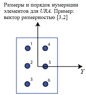
For URA The array elements are indexed from top to bottom in the leftmost column of the array and then in the following columns from left to right.
Element lattice — a grid of element positions URA
Rectangular (by default) | Triangular
Grid of element positions URA, set as rectangular or triangular.
-
Rectangular— aligns all elements in the row and column directions. -
Triangular— shifts the elements of an even row of a rectangular grid towards the positive direction of the row axis. The offset is half the distance between the elements according to the size of the row.
Dependencies
To use this parameter, set the Geometry parameter to URA.
Array normal — Direction of the normal to the pass grid:q[<br>] x for URA arrays or z for UCA arrays (default)
The direction of the normal to the lattice, given as x, y or z.
The elements of the flat lattices lie in a plane orthogonal to the selected direction of the array normal. The side view directions of the elements are directed along the direction of the normal.
| The value of the normal to the grid | The position of the elements and the direction of the side view |
|---|---|
|
The elements of the lattice lie in - planes. All vectors normal to the elements are directed along the X axis |
|
The elements of the lattice lie in - planes. All vectors normal to the elements are directed along the X-axis. |
|
The elements of the lattice lie in - planes. All vectors normal to the elements are directed along the axis . |
Dependencies
To use this parameter, set the Geometry parameter to URA or UCA.
Radius of UCA (m) is the radius of the UCA pass grid:q[<br>] 0.5 (default) | positive scalar
The radius of the array UCA, given as a positive scalar.
Dependencies
To use this parameter, set the Geometry parameter to 'UCA'.
Element positions (m) — position of the elements of the conformal lattice
[0;0;0] (default) | the matrix of positive values is 3 by N
The positions of the conformal elements, defined as a matrix of real values of dimension 3 by N, where N is the number of elements in the conformal array. Each column of this matrix represents a position ['x';'y';'z']array element in the local coordinate system of the array. The origin of the local coordinate system is (0,0,0). The units of measurement are meters.
Dependencies
To use this parameter, set the Geometry parameter to Conformal Array.
Element normals (deg) — the direction of the normal vectors of the elements of the conformal lattice
[0;0] | column vector 2 by 1 | the 2 by N matrix
The direction of the normal vectors of elements in a conformal lattice, defined as a 2-by-1 column vector or a 2-by-N matrix. N indicates the number of elements in the array. If the parameter is a matrix, each column specifies the direction of the normal of the corresponding element in the form [azimuth;elevation] relative to the local coordinate system. The local coordinate system aligns the positive X-axis with the direction of the normal to the conformal lattice. If the parameter value is a 2-by-1 column vector, the same pointing direction is used for all array elements.
Parameters of Element positions (m) and Element normals (deg) can be used to represent any arrangement in which pairs of elements differ by certain transformations. Transformations can combine translation, azimuth rotation, and elevation rotation. However, transformations that require rotation relative to the normal direction cannot be used.
To use this parameter, set the Geometry parameter to Conformal Array.
Taper — changing the radiation pattern of the elements of the antenna array
1 (default) | the complex scalar | the complex vector
The change in the radiation pattern of the antenna array elements is set as a complex scalar or a complex vector 1 by , where — the number of antenna array elements.
The coefficients that change the radiation pattern, also called element weights, multiply the responses of the antenna array elements. The coefficients change both the amplitude and the phase of the response to reduce the side lobes or the direction of the main axis of the response.
If the value of the Taper parameter is a scalar, then the same weight is applied to each element. If Taper is a vector, then a weight from the vector is applied to the corresponding element of the antenna array. The number of scales must correspond to the number of antenna array elements.
Subarray definition matrix — definition of elements belonging to subarrays of
The logical matrix
Set the selection of the subarray as a matrix M by N. M is the number of subarrays, and N is the total number of elements in the array. Each row of the matrix represents a subarray, and each entry in the row indicates when an element belongs to the subarray. If the record is zero, then the element does not belong to the subarray. A non-zero entry is a complex-valued weight applied to the corresponding element. Each row must contain at least one non-zero entry.
The phase center of each subarray is located in the geometric center of the subarray. The geometric center of the subarray depends on the Subarray definition matrix and Geometry parameters.
Dependencies
To use this parameter, set the Specify sensor array as parameter to Partitioned array.
Subarray steering method — specify the method for controlling the pass subarray:q[<br>] None (default) | Phase | Time
A method for managing a subarray, specified as one of
-
None -
Phase -
Time -
Custom
Dependencies
To use this parameter, set the Specify sensor array as parameter to Partitioned array or Replicated subarray.
Phase shifter frequency (Hz) is the frequency of the phase shift of the pass subarray:q[<br>] 3.0e8 (default) | a real positive scalar
The operating frequency of the rotary control phase shifters of the subarray, set as a positive real scalar. The units of measurement are hertz.
Dependencies
To use this parameter, set the value for Sensor array Partitioned array or Replicated subarray and set the Subarray steering method to Phase.
Number of bits in phase shifters — quantization bits of the phase shift of the control of the subarray
0 (default) | a non-negative integer
The quantization bits of the steering phase shift of the subarray, specified as a non-negative integer. A value of zero means that quantization is not performed.
Dependencies
To use this parameter, set the value for Sensor array Partitioned array or Replicated subarray and set the Subarray steering method to Phase.
Subarrays layout — specification of the position of the pass:q subarray[<br>] Rectangular (default) | Custom
Specify the location of identical subarrays as Rectangular or Custom.
When setting this parameter to Rectangular To place the subarrays, use the Grid size and Grid spacing parameters.
When setting this parameter to Custom to place the subarrays, use the Subarray positions (m) parameters and Subarray normals.
Dependencies
To use this parameter, set the Sensor array parameter to Replicated subarray
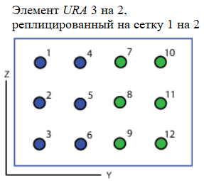
Grid size — The dimensions of the rectangular grid of the pass subarray:q[<br>] [1,2] (default)
The grid size of a rectangular subarray is set as a single positive integer or as a 1 by 2 vector string of positive integers.
If Grid size is an integer scalar, then the array has an equal number of subarrays in each row and each column. If Grid size is a 1 by 2 vector of the form [NumberOfRows, NumberOfColumns], then the first entry is the number of subarrays in each column. The second entry is the number of subarrays in each row. The line is positioned along the local axis y, and the column is along the local axis z. The figure shows how a subarray can be reproduced. URA the size is 3 by 2, using the grid size [1,2].
Dependencies
To use this parameter, set the Sensor array parameter to Replicated subarray and for the Subarrays layout parameter, the value Rectangular.
Grid spacing (m) — the distance between the subarrays on the rectangular grid
Auto (default) | a real positive scalar| a 1 by 2 vector with real positive numbers
The distance between the subarrays in a rectangular grid, defined as a positive real scalar, a 1-by-2 vector of positive real values, or Auto. The units of measurement are meters.
-
If Grid spacing is a scalar, then the distance between rows and the distance between columns are the same.
-
If Grid spacing is a 1 by 2 vector, the vector has the form
[SpacingBetweenRows,SpacingBetweenColumn]. The first entry specifies the distance between rows along the column. The second element sets the distance between the columns in the row. -
If the Grid spacing parameter is set to
Autowhen repeating, the distance between the elements of the subarray is preserved for both rows and columns when constructing a complete array. This parameter is only available when setting the Geometry parameter. howULAorURA.
Dependencies
To use this parameter, set the Sensor array parameter to Replicated subarray, and for the Subarrays layout parameter — Rectangular.
Subarray positions (m) — positions of the pass subarrays:q[<br>] [0,0;0.5,0.5;0,0] ( by default) | the real matrix is 3 by N
The positions of the subarrays in the custom grid, defined as a 3—by-N real matrix, where N is the number of subarrays in the array. Each column of the matrix represents the position of one subarray in the local coordinate system of the array. The coordinates are expressed as [x; y; z]. The units of measurement are meters.
Dependencies
To use this parameter, set the Sensor array parameter to Replicated subarray and for the Subarrays layout parameter, the value Custom.
Subarray normals — the direction of the normal vectors of the subarray
[0,0;0,0] (default)| the real matrix is 2 by N
Specify the directions of the normals of the subarrays in the array. The value of this parameter is a 2 by N matrix, where N is the number of subarrays in the array. Each column of the matrix defines the direction of the normal of the corresponding subarray in the form [azimuth;elevation]. The units of measurement of angles are degrees. The angles are set relative to the local coordinate system.
The Subarray positions and Subarray normals parameters can be used to represent any location in which pairs of subarrays differ by certain transformations. Transformations can combine translation, azimuth rotation, and elevation rotation. However, transformations that require rotation relative to the normal cannot be used.
Dependencies
To use this parameter, set the Sensor array parameter to Replicated subarray, and for the Subarrays layout parameter — Custom.