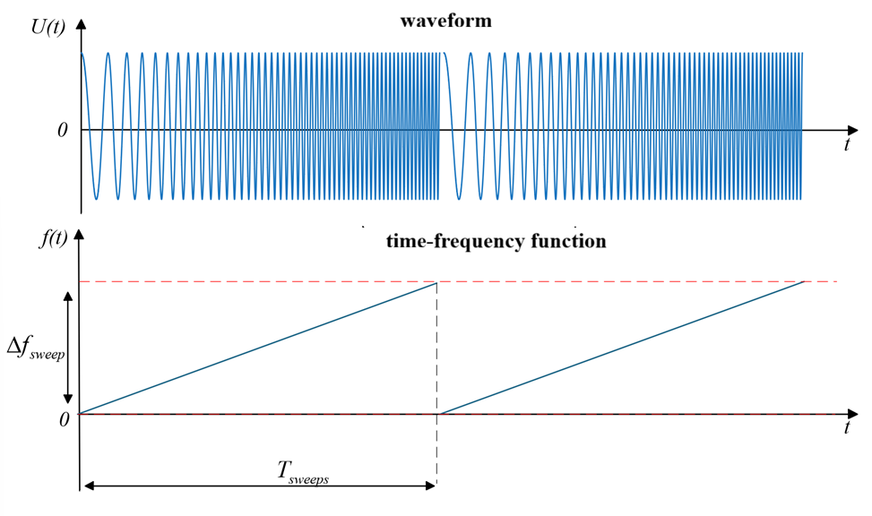
EngeePhased.FMCWWaveform
A continuous frequency modulated signal generator.
| Library |
|
| Block |
Description
System object EngeePhased.FMCWWaveform It is a continuous frequency modulation (FM) signal generator.
To generate a continuous FM signal, follow these steps:
-
Create an object EngeePhased.FMCWWaveform and set its properties.
-
Call the object with arguments as if it were a function.
To learn more about how to work with system objects, see Engee System Objects.
Syntax
Creation
-
waveform = EngeePhased.FMCWWaveform()— creates a system objectwaveforma continuous FM signal generator with default properties. -
waveform = EngeePhased.FMCWWaveform(Name=Value)— creates a system objectwaveforma continuous FM signal generator with specified properties in the form of a pairName=Value, whereName— the name of the property, andValue— the appropriate value. You can specify multiple pairs «name-value» the order of the pairs does not matter. Unspecified properties retain their default values.
Arguments
Output arguments
Y — continuous FM signal
+
the complex vector
Details
If the property is OutputFormat has a value "Samples", then Y contains [Property:numSamples] counts.
If OutputFormat has value "Sweeps", then Y contains NumSweeps pulses. In addition, if SweepDirection matters "Triangle", then each pulse is half the period.
| Типы данных |
|
| Support for complex numbers |
yes |
Features
#
SampleRate —
sampling rate of the output signal
Real number
Details
The sampling frequency of the signal in the form of a positive scalar. Units of measurement — Hz.
By default — 1e6.
#
SweepTime —
the period of the modeling signal
Scalar / vector of real numbers
Details
Specify the period of the modeling signal in the form of a vector of positive real numbers.
The units of measurement are seconds.
If for a property SweepDirection value set "Triangle" The pulse time is equal to half the period, since each period consists of an upswing and a downswing.
If for the property SweepDirection value set "Up" or "Down", the time of the sweep pulse is equal to the period.
To realize the changing pulse time, specify SweepTime like a vector. The signal uses successive elements of the vector as the pulse time for successive periods of the signal. If the last element of the vector is reached, the process continues cyclically from the first element of the vector.
If the properties SweepTime and SweepBandwidth are set as a vector, they must have the same length.
By default — 1e−4.
#
SweepDirection —
direction of frequency deviation
String
Details
Specify the direction of frequency deviation: "Up", "Down", "Triangle". For more information, see Additional Info.
#
SweepInterval —
frequency deviation interval
String
Details
The frequency deviation interval, set as "Positive" (by default) or "Symmetric":
-
"Positive"— the frequency of the signal will vary in the interval from0beforeB, whereB— the width of the deviation bar in the property SweepBandwidth. -
"Symmetric"— the frequency of the signal will vary in the interval from−B/2beforeB/2.
#
OutputFormat —
Output format
String
Details
The format of the output signal in the form "Sweeps" (by default) or "Samples":
-
If you set this property to
"Sweeps", then the output of the unit consists of several pulses. The number of pulses is the value of the property NumSweeps. -
If you set this property to
"Samples", then the output of the block consists of several samples. The number of samples is the value of the property [Property:numSamples].
#
NumSamples —
number of samples of the output signal
Real number
Details
The number of samples of the output signal, specified as a positive integer.
By default — 100.
Dependencies
To use this property, set the property to OutputFormat value "Samples".
#
NumSweeps —
number of pulses of the output signal
Real number
Details
The number of pulses in the output signal, specified as a positive integer.
Dependencies
To use this property, set the property to OutputFormat value "Sweeps".
By default — 1.
#
SweepBandwidth —
frequency deviation
Scalar / vector of real numbers
Details
The bandwidth of a signal with continuous FM, specified as a vector of positive real numbers. Units of measurement — Hz.
By default — 10e4.
Methods
Examples
Continuous signal generation with linear frequency modulation
Details
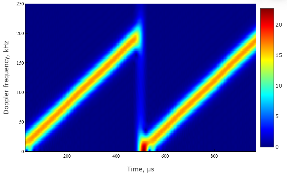
Let’s form a continuous signal with linear frequency modulation with sampling frequency 1 MHz, the rise period 500 iss and frequency deviation 200 kHz.
Initialize the parameters.
fs = 1e6 # Частота дискретизации, Гц
sweep_time = 500.e-6 # период нарастания, с
sweep_band = 2e5 # Гц, ширина спектра
out_type = "Sweeps" # тип выходного сигнала "Pulses" — по импульсам

num_sweeps = 2 # количество пил
sw_dir = "Up" # направление изменения частоты
sweep_int = "Positive"; # тип пилы ["Positive","Symmetric"]
Let’s use EngeePhased.FMCWWaveform to create a probe signal system object fmcw.
fmcw = EngeePhased.FMCWWaveform(
    SampleRate = fs,
    SweepTime = sweep_time,
    SweepBandwidth = sweep_band,
    SweepDirection = sw_dir,
    SweepInterval = sweep_int,
    NumSweeps = num_sweeps
);
Making a call to the system object EngeePhased.FMCWWaveform using the fmcw variable.
fmcw_sig = fmcw();Using the function plot Let’s construct an oscilloscope in the form of an IQ component, a module, and a phase of the signal.
# построение IQ-компонент
t_grid = range(start = 0,step = 1/fs,length = length(fmcw_sig)) * 1e6 # сетка времени, мкс
fig1 = plot(t_grid,real.(fmcw_sig),title = "синфазная составляющая",lab="",ylab="Амплитуда")
fig2 = plot(t_grid,imag.(fmcw_sig),title = "квадратурная составляющая",lab="",xlab = "Время, мкс",ylab="Амплитуда");

plot(fig1,fig2,layout = (2,1))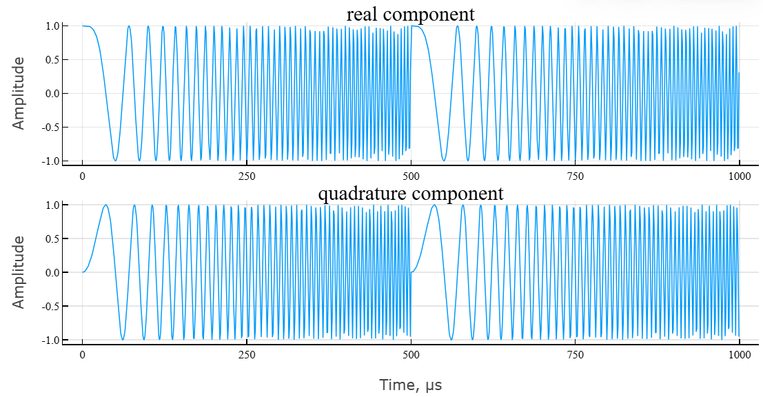
# построение модуля и фазы сигнала
fig3 = plot(t_grid,abs.(fmcw_sig),title = "Модуль комплексного сигнала",lab="",ylab="Амплитуда");
fig4 = plot(t_grid,angle.(fmcw_sig)*180/pi,title = "Аргумент комплексного сигнала",lab="",xlab = "Время, мкс",ylab="Фаза, град.");

plot(fig3,fig4,layout = (2,1))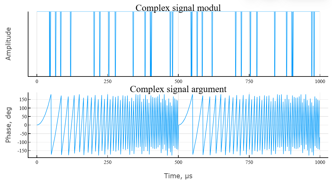
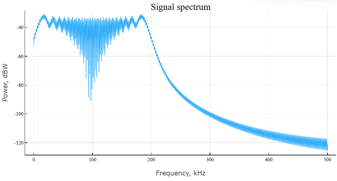
The main characteristic of the signal is the frequency spectrum and the spectrogram. Let’s use the built-in function periodogram.
# расчет спектра сигнала
spec_LFM,f = EngeePhased.Functions.periodogram(
    fmcw_sig, # исходный сигнал
    EngeeDSP.Functions.hamming(size(fmcw_sig)...),
    8192; # длина частоты дискретизации
    out = :data, # тип выхода
    fs = fs, # частота дискретизации
    spectrumtype = "power" # тип спектра
);
Visualize the result using the function plot.
plot(
    f * 1e-3,
    EngeePhased.Functions.mag2db.(spec_LFM),
    lab="", xlab = "Частота, кГц",
    ylab = "Мощность, дБВт",
    title = "Спектр сигнала"
)
To calculate the spectrogram, we use the built-in function spectrogram.
# расчет спектрограммы
spectgm_lfm,f1,t1 = EngeeDSP.Functions.spectrogram(
    real.(fmcw_sig);
    nfft = 512, # длина БПФ
    window = EngeeDSP.Functions.hamming(64),
    noverlap = 60, # перекрытие окна
    spectrumtype = "power",  # тип спектра — по мощности
    freqrange = "onesided", # диапазон спектра — односторонний
    out = :data, # тип выхода — массив данных
    fs = fs # частота дискретизации
);
We visualize the result of the spectrogram calculation using the function heatmap.
# построение спектрограммы
heatmap(
    t1[:]*1e6,f1[:]*1e-3,
    abs.(spectgm_lfm),color = :jet,
    xlab = "Время, мкс",
    ylab = "Частота Доплера, кГц",
    ylims = (0,250)
)
Additional Info
Triangular frequency deviation
Details
In each period of triangular deviation, the signal rises with a slope. and then it descends with a slope , where — frequency deviation, and — pulse time. The pulse period is .


Algorithms
The analytical recording of a signal with continuous frequency modulation under the classical sawtooth modulation law has the form:
where
-
— scan time (duration of one modulation period);
-
— frequency deviation (bandwidth adjustment);
-
— the amplitude;
-
— the initial frequency.
To generate a continuous frequency modulated signal, the following parameters must be set:
-
filter sampling rate ;
-
scan time (modulation period) ;
-
frequency deviation ;
-
the shape (direction) of the frequency change (sawtooth or triangular).