Digital Filter Editor
Filter Designer ![]() — This is an Engee application designed for flexible configuration and design of various types of digital filters. With this tool, you can design filters that meet various frequency response requirements, providing efficient signal filtering in various fields such as digital signal processing, telecommunications, and audio technology.
— This is an Engee application designed for flexible configuration and design of various types of digital filters. With this tool, you can design filters that meet various frequency response requirements, providing efficient signal filtering in various fields such as digital signal processing, telecommunications, and audio technology.
To open the filter editor, go to the Engee application window  and select Filter Designer
 ![]() . The digital filter editor opens in a separate browser tab and takes some time to download.:
. The digital filter editor opens in a separate browser tab and takes some time to download.:
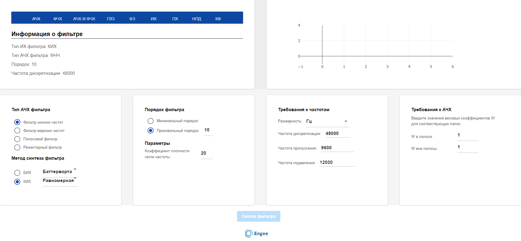
In the editor, you can select the filter type, synthesis method, filter order, and set frequency parameters depending on specific tasks. These functions allow you to create filters with specified characteristics.
After all the settings are set, click the Filter Synthesis button at the bottom of the editor to display information on the charts.:

Configuring the filter
The filters are configured using four modules.
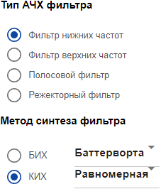
Frequency response filter type
-
Module Frequency response filter type — selection of the type of amplitude-frequency response of the filter.
-
Low—pass filter (low-pass filter) - passes low frequencies and suppresses high frequencies.
-
High—pass filter (UHF) - passes high frequencies and suppresses low ones.
-
Bandpass filter — passes frequencies in a certain range and suppresses the rest.
-
Notch filter — suppresses frequencies in a certain range and skips the rest.
-
-
The method of filter synthesis is the choice of an algorithm for filter formation.
-
BIH (infinite impulse response) is a filter with an infinite response to a single pulse.
-
A Butterworth filter with the most flat amplitude characteristic in the passband.
-
Chebysheva1 (the first type) is a filter with ripples in the bandwidth and a sharp drop beyond it.
-
Chebysheva2 (of the second type) is a filter with pulsations in the suppression band and a smooth drop in the passband.
-
Elliptical is a filter with ripples in both the passband and the suppression band.
-
-
FIR (finite impulse response) is a filter with a finite response to a single pulse.
-
Uniform is a filter with a uniform distribution of coefficients.
-
Window filter is a filter created using window functions to reduce side lobes.
-
-
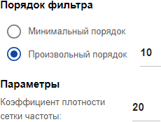
Filter order
-
Module Filter order is the choice of the degree of the polynomial that determines the complexity of the filter.
-
The minimum order is the filter with the smallest possible number of coefficients.
-
An arbitrary order is a filter with a user—defined number of coefficients.
-
-
Parameters
-
The frequency grid density coefficient is a parameter that determines the sampling accuracy of the frequency axis.
-
-
If you select the synthesis method Windowed for the FIR parameter (final impulse response), the parameter window will change its appearance:
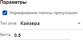
_ Brief description of window types_
Type Description Bartlett’s
A triangular window, which gradually decreases to zero at the ends, is used to minimize spectrum leakage.
Bartleta_hanna
A smoothed window that combines the characteristics of Bartlett and Hannah windows, providing good side lobe suppression.
Blackman’s
A window with a high degree of side lobe suppression and a wide main lobe, suitable for accurate spectral analysis.
Blackman_harris
A variant of the Blackman window with even greater side lobe suppression is often used in applications with a high dynamic range.
Bomana
A symmetrical window using coefficients that ensure a balance between the width of the main lobe and the level of the side lobes.
Gauss
A window with a Gaussian distribution that provides an optimal compromise between the time and frequency domain.
The Kaiser
A parametric window that allows you to adjust the compromise between the width of the main lobe and the level of the side lobes.
Nuttola
A window with smooth transition and good side lobe suppression is used in spectral analysis.
Parzen
A smooth window with a small spectrum leakage is used in signal analysis tasks.
Rectangular
A window with no smooth transition minimizes spectrum leakage, but creates high side lobes.
With a flat top
A window with an extended flat area at the top to improve the accuracy of the amplitude in spectral analysis.
Taylor’s
A window with an adjustable number of side lobes, used to improve the suppression of side lobes.
Triangular
A simple window with linear reduction to zero is often used to smooth data.
Tukey
A window with a parametrically variable shape that transitions from rectangular to cosine.
Hannah
A cosine window with a smooth decrease to zero at the ends is often used to minimize spectrum leakage.
Hamming
A modification of the Hanna window with a lower attenuation coefficient at the ends is used to filter the signals.
Chebysheva
A window with a uniform oscillation of the side lobes, minimizing the level of the side lobes.
Frequency characteristics
-
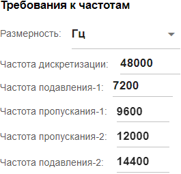
Module Frequency requirements — setting the key frequency characteristics of the filter.
-
Dimension — frequency units (Hz, kHz, MHz, GHz).
-
Sampling rate is the number of samples of a signal in one second.
-
Bandwidth is the frequency below which the signal passes through the filter.
-
Suppression frequency — the frequency above which the signal is suppressed.
-
-
Depending on the selected type of frequency response filter, the number of frequency characteristics of the filter changes, for example:
Low-income tax Bandpass filter 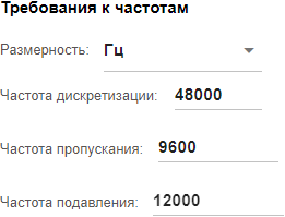
Frequency response requirements
-
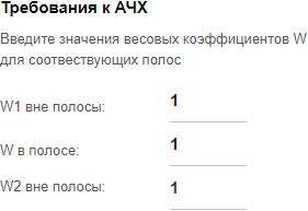
Module Frequency response requirements — enter the values of the W weighting coefficients for the corresponding bands:
-
W in the bandwidth is the weighting factor in the bandwidth.
-
W out of band is the out—of-band weighting factor.
-
-
Depending on the selected type of frequency response filter, the number of weighting coefficients W changes, for example:
Low-income tax Bandpass filter 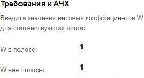
|
If you select the synthesis method Windowed for the FIR parameter (final impulse response), then the coefficient settings will be disabled for the module Frequency response requirements.:
|
The Filter Information section shows the parameters and characteristics of the filter. The application provides the following features for graphical and numerical display of the characteristics of the projected filter:
-
Frequency response is the amplitude—frequency characteristic of the filter, showing the dependence of the signal transmission coefficient on the frequency;
-
The frequency response is the phase—frequency characteristic of the filter, which shows the dependence of the phase shift of the signal on the frequency;
-
Frequency response and frequency response — joint display of amplitude-frequency and phase-frequency characteristics;
-
GVZ is a group delay time that shows the average delay of a signal at various frequencies.;
-
FZ — phase delay, showing the time delay of the signal phase;
-
THEY are the impulse response, which shows the response of the filter to a single pulse (delta function);
-
PX is a transient characteristic showing the response of the filter to a single step function (Heaviside function);
-
NPD — zero is a pole diagram that defines the points of reversal of the polynomial of the numerator (zeros) and the denominator (poles).
-
CF are the filter coefficients (coefficients of the numerator and denominator of the filter transfer function).
Working with charts
When hovering over the chart, the following options are available:
-
Download plot as PNG (download graph as PNG)

-
Zoom (zoom in)

-
Box select (area selection)

-
Lasso select

-
Pan (pan)

-
Zoom in (zoom in)

-
Zoom out (zoom out)

-
Autoscale (scale automatically)

-
Reset axes

Uploading results
To download the synthesis results, click CF (filter coefficients) in the Filter Information module.:
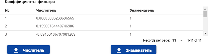
The Numerator and Denominator columns represent the coefficients of the digital filter transfer function.
Clicking on the Numerator or Denominator will download txt files — num.txt for the numerator and denom.txt for the denominator. In this case, all denominator values are equal to one, which may indicate that a FIR (Finite Impulse Response) filter with a finite impulse response is being considered, where the denominator is a constant.
Thus, the digital filter editor allows you to create custom filters with preset parameters, which helps in efficient signal processing.