Radar Equation Calculate
Radar Equation Calculate ![]() — This is an Engee application designed to calculate the basic radar equation for monostatic footnotes:[A monostatic radar system is a radar system in which the transmitter and receiver are located in the same location or very close to each other. Such radars emit a radio signal that is reflected from an object and then received by the same device.] and bistatic[1] radar systems.
— This is an Engee application designed to calculate the basic radar equation for monostatic footnotes:[A monostatic radar system is a radar system in which the transmitter and receiver are located in the same location or very close to each other. Such radars emit a radio signal that is reflected from an object and then received by the same device.] and bistatic[1] radar systems.
The detailed description of the radar equation
The basic radar equation, taking SNR into account, looks like this:
,
where:
-
— Signal-to-noise ratio (SNR), shows how strong the useful signal is compared to noise;
-
— the power of the received signal (W) reflected from the target;
-
— noise power (W), determines the level of background noise in the system;
-
— the power of the transmitter (W), determines the intensity of the emitted signal;
-
— the gain of the transmitting antenna (dimensionless value), shows how much the antenna focuses energy in the desired direction;
-
— the gain of the receiving antenna (dimensionless value), shows how much the antenna amplifies the received signal;
-
— the wavelength of the emitted signal (m) is related to the radar frequency by the formula , where — the speed of light;
-
— the range to the target (m), shows the distance at which the object is located;
-
— total losses in the system (dimensionless value), takes into account all possible signal losses due to the atmosphere, antenna imperfections and other factors;
-
— Boltzmann constant ( J/K), a constant used to calculate thermal noise;
-
— the noise temperature of the system (K), is determined by the ambient temperature and the electronics of the radar;
-
— receiver bandwidth (Hz), determines which part of the frequency spectrum the radar receives (a wide band can transmit more noise);
-
— the receiver’s noise factor (a dimensionless value), shows how much the receiver itself contributes additional noise to the signal.
Based on the formula, it follows that:
-
If the power of the transmitter is known and SNR ( ), then the maximum range can be calculated on which the radar is able to detect the target:
.
-
If the range is known and SNR, then you can determine what the power of the transmitter is it is needed for the operation of the radar:
.
-
If the range is known and the power of the transmitter , then it is possible to calculate the expected SNR:
.
To open the application, go to the Engee workspace and in the upper-left corner in the section Engee Applications ![]() choose Radar Equation Calculate
choose Radar Equation Calculate ![]() . The application works in a separate browser tab and by default looks like this:
. The application works in a separate browser tab and by default looks like this:
The radar equation solved using the application relates the range to the target, the transmitted power and the signal-to-noise ratio (SNR) of the received signal. Therefore, using the application, you can:
-
Solve the problem of determining the maximum range to the target based on the power of the transmitted radar signal and the specified SNR of the received signal;
-
Calculate the required transmitter power based on the known range to the target and the specified SNR of the received signal;
-
Calculate the SNR value of the received signal based on the known range and power of the transmitter.
Working with the app
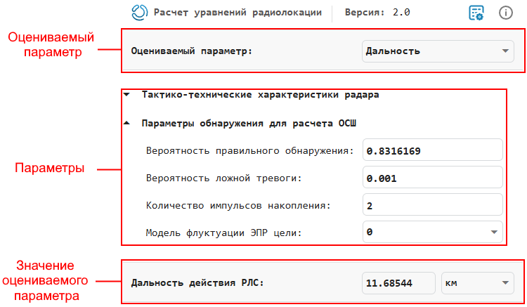
Three conditional sections are used to work with the application.:
-
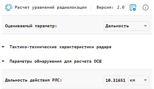
The estimated parameter is the section where the parameter for calculation is selected. The value of the selected parameter will be displayed in the Value of the evaluated parameter section. The following options are available for selection:
-
Range— the maximum range to the target based on the power of the radar transmitter and the desired received SNR; -
Peak power— the power required for transmission, based on the known range of the target and the desired received SNR; -
SNR— the value of the received SNR based on the known transmission range and power.
-
-
Parameters is the section where the parameter values are set. Each parameter has a default value that can be changed. The unit of measurement can be selected to the right of the value field.

The Parameters section contains all available application parameters with explanations.
-
The value of the estimated parameter is the calculated result of the basic radar equation for the parameter selected in the Estimated parameter section.
Parameters
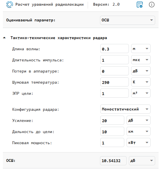
The following is an overview of the application settings. Their number and type depend on the selected value in the Estimated parameter section and on the Radar Configuration parameter (see below).
Wavelength — the wavelength of the radar radar
+
0.3 (default)
Details
Specify the radar wavelength in m (default), cm or mm.
Wavelength is the ratio of the speed of propagation of a wave to the frequency. For electromagnetic waves, the speed of propagation is equal to the speed of light.
If we denote the speed of light by , and the frequency of the wave (in hertz) through , then the equation for the wavelength will be .
Pulse duration — duration of a single pulse
+
1 (default)
Details
Specify the duration of a single pulse in ms (default), ms or s.
Losses in equipment — the totality of all signal power losses occurring in the system hardware
+
0 (default)
Details
Specify the losses in the equipment in dB (default) or absolute units.
Hardware losses are the total loss factor, which includes losses that occur in hardware components and during propagation to and from the target.
Noise temperature — noise temperature of the system
+
290 (default)
Details
Specify the noise temperature of the system in K (default) or °C.
The noise temperature of a system is the product of the system temperature and the noise factor.
Target EPR — effective scattering area (ESR) of the target
+
1 (default)
Details
Specify the EPR of the goal in (by default), .
The parameter characterizes how well an object reflects radio waves back to the radar. The higher the EPR, the more visible the target is to the radar, and vice versa.
-
The EPR of the target * does not change over time (does not fluctuate).
Radar configuration — type of radar system
+
Monostatic (default)
Details
Specify the type of radar system:
-
Monostatic(default) — The transmitter and receiver are located in the same location (monostatic radar). -
Bistatic— The transmitter and receiver are not spaced apart (bistatic radar).
Gain — the gain of the transmitter and receiver
+
20 (default)
Details
Specify the gain of the transmitter and receiver in dB (default) or absolute units.
When the transmitter and receiver are positioned together (monostatic radar), the transmission and reception gain coefficients are equal.
Dependencies
This parameter is enabled only if the Radar Configuration parameter is set to Monostatic.
Peak power — peak power of the transmitter
+
20 (default)
Details
Specify the peak power of the transmitter in kW (default), MW, W, or dBW.
Dependencies
This parameter is enabled only if the parameter Evaluated parameter is set to Range or SNR.
SNR — the minimum ratio of the output signal to the receiver noise
+
10 (default)
Details
Specify the SNR value or calculate the SNR value using the SNR detection specification.
It is possible to calculate the SNR required to achieve a certain probability of detection and the probability of a false alarm using the Shniedman equation. To calculate the SNR value:
-
Click on the section Detection parameters for calculating SNR to open additional SNR settings.:
-
Enter the values for the parameters Probability of correct detection, Probability of false alarm, Number of accumulation pulses and Target EPR fluctuation model.
Dependencies
This parameter is enabled only if the parameter Evaluated parameter is set to Range or Peak power.
Probability of correct detection — the probability of detection used to estimate SNR
+
0.8102924 (default)
Details
Specify the detection probability used to estimate the SNR using the Shniedman equation.
Dependencies
This parameter is enabled only if the parameter Evaluated parameter is set to Range or Peak power.
False Alarm Probability — False alarm probability used to estimate SNR
+
0.001 (default)
Details
Specify the probability of a false positive used to estimate the SNR using the Shniedman equation.
Dependencies
This parameter is enabled only if the parameter Evaluated parameter is set to Range or Peak power.
Number of accumulation pulses — number of pulses used to estimate SNR
+
1 (default)
Details
Specify the number of pulses of incoherent radar accumulation used in the Shnidman equation to calculate the SNR.
Use multiple pulses to reduce the transmitted power while maintaining maximum target range.
Dependencies
This parameter is enabled only if the parameter Evaluated parameter is set to Range or Peak power.
Target EPR Fluctuation model — Drilling case number used to estimate SNR
+
0 (default)
Details
Specify the Drilling model number used to estimate the SNR using the Shnydman equation:
-
0— non-oscillating impulses; -
1— decorrelation from scan to scan. Rayleigh/exponential distribution — a series of randomly distributed scatterers without a dominant scatterer; -
2— pulse-to-pulse decorrelation. Rayleigh/exponential distribution — a series of randomly distributed scatterers without a dominant scatterer; -
3— decorrelation from scan to scan. Chi-square distribution with 4 degrees of freedom. Number of diffusers with one dominant; -
4— pulse-to-pulse decorrelation. Chi-square distribution with 4 degrees of freedom. Multiple diffusers with one dominant.
The Drilling case numbers characterize the problem of detecting fluctuating pulses in terms of:
-
The decorrelation model for received pulses;
-
The distribution of diffusers that affects the probability density function (OPF) of the effective scattering area (ESR) of the target.
The Drilling examples consider all combinations of two decorrelation models (from scan to scan; from pulse to pulse) and two EPR FPGAs (based on the presence or absence of a dominant diffuser).
Dependencies
This parameter is enabled only if the parameter Evaluated parameter is set to Range or Peak power.
Range to target — distance to target
+
10 (default)
Details
Specify the range to the target in m, km (default), miles, or nautical miles.
Dependencies
This parameter is enabled only if the parameter Evaluated parameter is set to Peak power or SNR, and for the parameter Radar configuration the value is selected Monostatic.
Range from the transmitter — range from the transmitter to the target
+
10 (default)
Details
Specify the range from the transmitter in m, km (default), miles, or nautical miles.
If the transmitter and receiver are not located in the same place (bistatic radar), then specify the range of the transmitter separately from the range of the receiver.
Dependencies
This parameter is enabled only if the parameter Evaluated parameter is set to Peak power or SNR, and for the parameter Radar configuration the value is selected Bistatic.
Range from receiver — distance from target to receiver
+
10 (default)
Details
Specify the range from the receiver in m, km (default), miles, or nautical miles.
If the transmitter and receiver are not on the same line (bistatic radar), then specify the range of the receiver separately from the range of the transmitter.
Dependencies
This parameter is enabled only if the parameter Evaluated parameter is set to Peak power or SNR, and for the parameter Radar configuration the value is selected Bistatic.
Parameters in the code (export from the application)
The application generates code that can be used in various modeling and programming tasks, such as those described in Radar.
To do this, click the button in the upper-right corner of the application.
 . After in the window File Browser
 a file named RadarEquationScript_GGGG-MM-DD_HH will be created automatically.:MM: SS.MSS.jl with code in Julia language. The file will list all the parameters and their values from the application at the time of pressing the button. For example:
-
In the application:
-
In the created one .jl file:
# {docs_engee} code
# Generated in {docs_engee} version 25.3.
# Generated on 2025-03-24 12:22:56.919

# All values are presented in system units

wavelength = 0.3 # Wavelength (m)
pwidth = 1.0e-6 # Pulse duration (s)
sysloss = 0.0 # System loss (dB)
noisetemp = 290.0 # Noise temperature (K)
rcs = 1.0 # EPR, m^2
gain = 20.0 # Antenna gain (dB)
tgtrng = 10000.0 # Range (m)
pkpow = 1000.0 # Peak transmitter power (W)
snr = radareqsnr(wavelen, tgtrng, pkpow, pwidth,
		RCS = rcs, Gain = gain,
		Loss = sysloss, Ts = noisetemp)