HDL FIFO
Storing a sequence of input samples in a first-in-first-out (FIFO) register.
blockType: SubSystem
|
Path in the library: |

Description
The HDL FIFO block stores a sequence of input samples in a FIFO (first in, first out) register. The data written first into the FIFO register comes out first. The block implementation resembles FIFO block in hardware platforms in terms of functionality and behaviour.
Ports
Input
#
In
—
input signal
scalar
Details
Data input signal to the unit.
When data is written to the block, the newest data is placed at the end of the register. The block writes subsequent data following this entry.
| Data types |
|
| Complex numbers support |
Yes |
#
Push
—
push signal
scalar
Details
When 1 is received on this port, the block places the data from port In at the end of the FIFO register.
| Data types |
|
| Complex numbers support |
No |
#
Pop
—
read control signal
scalar
Details
When a 1 value is received on this port, the block unloads the first item from the FIFO register and holds that value on the Out port.
| If two or more input control ports are triggered in the same time step, first a read is performed at the Pop signal, and then a write is performed at the Push signal. |
| Data types |
|
| Complex numbers support |
No |
#
rst
—
reset control signal
scalar
Details
When the reset port receives the value 1, it resets the Empty, Full and Num outputs of the block HDL FIFO.
| Data types |
|
| Complex numbers support |
No |
Output
#
Out
—
data output signal
scalar
Details
Signal to output data from the FIFO block. When a read from FIFO operation is performed, the data that was written first to the FIFO register is fetched from the FIFO and held at the output.
| Data types |
|
| Complex numbers support |
Yes |
#
Empry
—
empty register indication signal
scalar
Details
A control signal output from the FIFO equal to 1 when there is no data in the FIFO register and a read operation cannot be performed.
| Data types |
|
| Complex numbers support |
No |
#
Full
—
register full indication signal
scalar
Details
A control signal output from the FIFO that is 1 when the FIFO register is full and cannot accept any more data.
| Data types |
|
| Complex numbers support |
No |
#
Num
—
number of records
scalar
Details
The amount of data that is currently in the FIFO register.
-
Num is incremented by
1for each data you write to the FIFO. -
Num decreases by
1for each data you read from the FIFO.
| Data types |
|
| Complex numbers support |
No |
Parameters
Main group
# Register size — number of records
Details
Specify the number of entries that the FIFO register can contain.
The minimum value for Register size is 4.
| Default value |
|
| Program usage name |
|
| Tunable |
No |
| Evaluatable |
Yes |
#
Mode —
mode of operation
Classic | FWFT
Details
Specify the FIFO operation mode.
Using FWFT' mode, you can look ahead and see the data at the beginning of the FIFO queue without having to perform a read operation. The `FWFT mode is especially useful when you apply backpressure with AXI4-Stream interfaces.
| Values |
|
| Default value |
|
| Program usage name |
|
| Tunable |
No |
| Evaluatable |
Yes |
# The ratio of output sample time to input sample time — sampling rate coefficient
Details
Specify the ratio of the output sampling period to the input sampling period.
By default, this ratio is 1, which means that the In and Push inputs and Out and Pop outputs operate at the same sampling rate.
Inputs and outputs may operate at different sampling periods. Use a positive integer or 1/N, where N is a positive integer. For example, if 1/2 is entered, the sampling period of the outputs will be half the sampling period of the inputs, i.e. the outputs will run faster. The signals of Full, Empty and Num ports work with higher speed.
| Default value |
|
| Program usage name |
|
| Tunable |
No |
| Evaluatable |
Yes |
#
Push onto full register —
overflow condition on the Push port
Ignore | Warning | Error
Details
Specify how the block should react when writing to a filled FIFO.
| Values |
|
| Default value |
|
| Program usage name |
|
| Tunable |
No |
| Evaluatable |
Yes |
#
Pop empty register —
overflow condition on port Pop
Ignore | Warning | Error
Details
Specify how the block should react to reading from an empty FIFO.
| Values |
|
| Default value |
|
| Program usage name |
|
| Tunable |
No |
| Evaluatable |
Yes |
# On empty register indicator port (Empty) — empty register indication port
Details
Select this check box to enable the empty register display port.
This port outputs 1 when the FIFO register is empty and 0 when the FIFO contains one or more data records.
| Default value |
|
| Program usage name |
|
| Tunable |
No |
| Evaluatable |
Yes |
# On full register indicator port (Full) — register fullness indication port
Details
Select this check box to enable the register full indication port.
This port outputs 1 when the FIFO register is full.
| Default value |
|
| Program usage name |
|
| Tunable |
No |
| Evaluatable |
Yes |
# On number of register entries port (Num) — port of information about the number of entries in the register
Details
Select this check box to enable the register count information port.
This port outputs the amount of data that is currently available in the FIFO queue.
| Default value |
|
| Program usage name |
|
| Tunable |
No |
| Evaluatable |
Yes |
# On local reset port (rst) — local reset port
Details
Select this check box to enable the optional local reset port rst.
| Default value |
|
| Program usage name |
|
| Tunable |
No |
| Evaluatable |
Yes |
Signal settings
#
Data type —
data type
Float64 | Float32 | Float16 | Int8 | UInt8 | Int16 | UInt16 | Int32 | UInt32 | Int64 | UInt64 | Int128 | UInt128 | Bool | Fixed-point
Details
Specify data type. Defined as:
-
Float64. -
Float32 -
Float16 -
Int8 -
`UInt8
-
`Int16
-
`UInt16
-
Int32 -
`UInt32
-
Int64 -
UInt64 -
Int128 -
`UInt128
-
Bool -
Fixed-point
| Values |
|
| Default value |
|
| Program usage name |
|
| Tunable |
No |
| Evaluatable |
Yes |
# Data fixed-point type — fixed-point data type
Details
Specify the fixed-point data type.
| Default value |
|
| Program usage name |
|
| Tunable |
No |
| Evaluatable |
Yes |
#
Signal type —
signal type
Real | Complex
Details
Specify the type of signal. Defined as:
-
Real. -
Complex
| Values |
|
| Default value |
|
| Program usage name |
|
| Tunable |
No |
| Evaluatable |
Yes |
# Sample time — sampling period
Details
The sampling period specified as a positive number.
| Default value |
|
| Program usage name |
|
| Tunable |
No |
| Evaluatable |
Yes |
Algorithms
*FIFO write operation
This figure shows a write operation. The Push input port acts as the enable signal for the write operation. In the figure, data_in denotes this signal.
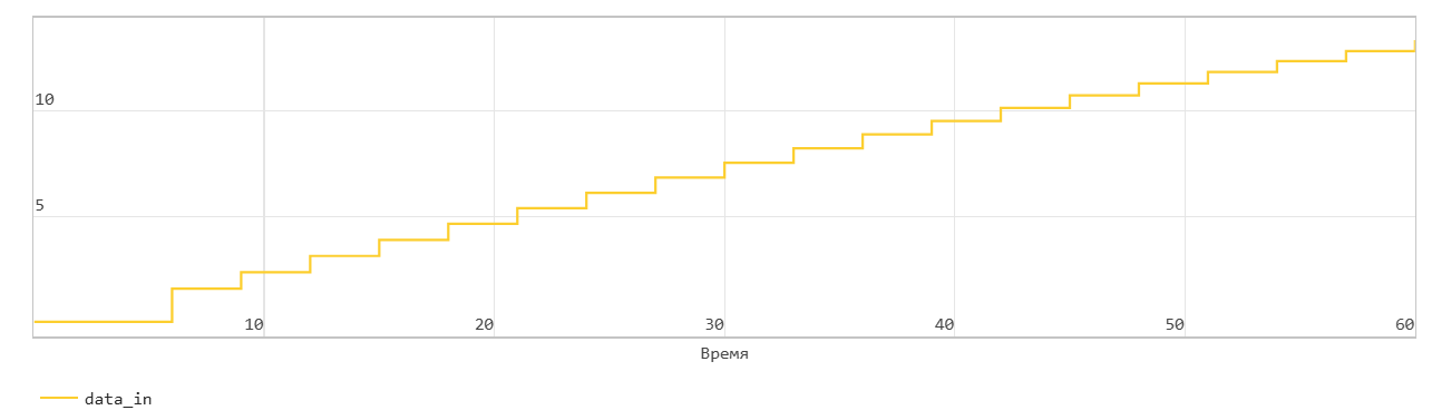

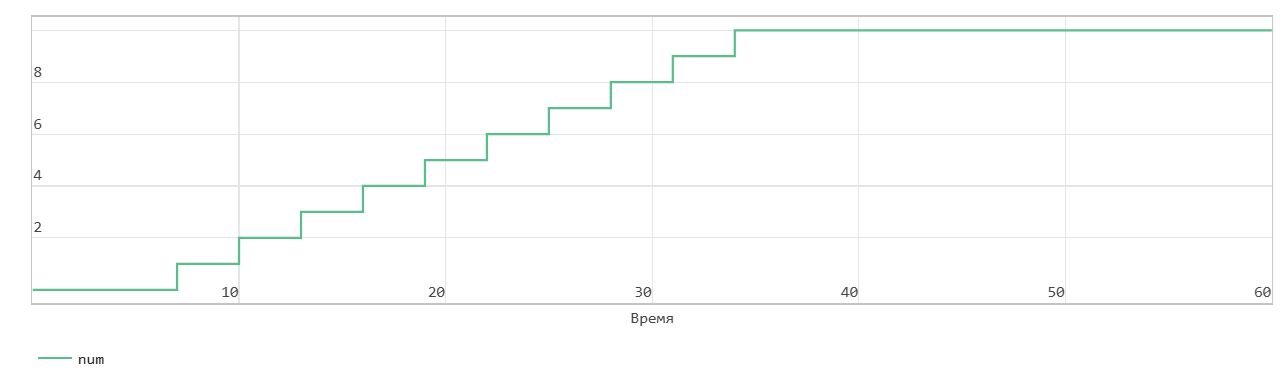
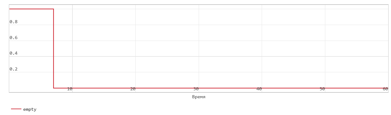
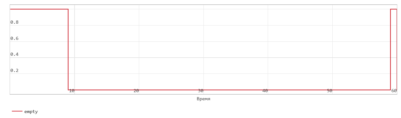
When the data_in signal is 0, the block does not write data to the FIFO, but sets the Empty flag.
When the data_in signal becomes 1, the block transfers the din signal on the In input port to the end of the FIFO register in the next time step. The Num signal indicates the amount of data in the FIFO register. Each time you write data to the FIFO, the Num signal is incremented by 1. At time step 6, data_in is equal to 1. At the next time step, data_in is 7, data is written to the FIFO. The Num signal is incremented by 1 and the Empty flag is cancelled.
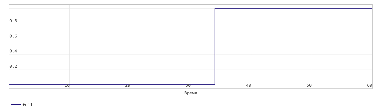
This FIFO uses the register size specified by the Register size parameters. By default, the register size is 10. In the figure, when the Num signal becomes equal to 10 at time step 34, the Full signal is asserted. After the Full signal becomes equal to 1, if you write more data to the FIFO, the block generates a warning.
*Classical FIFO read operation.
This figure shows a read operation. The Pop input port acts as the enable signal for the read operation. In the figure, read_en denotes this signal.
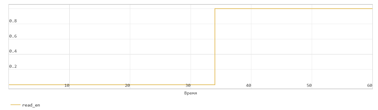
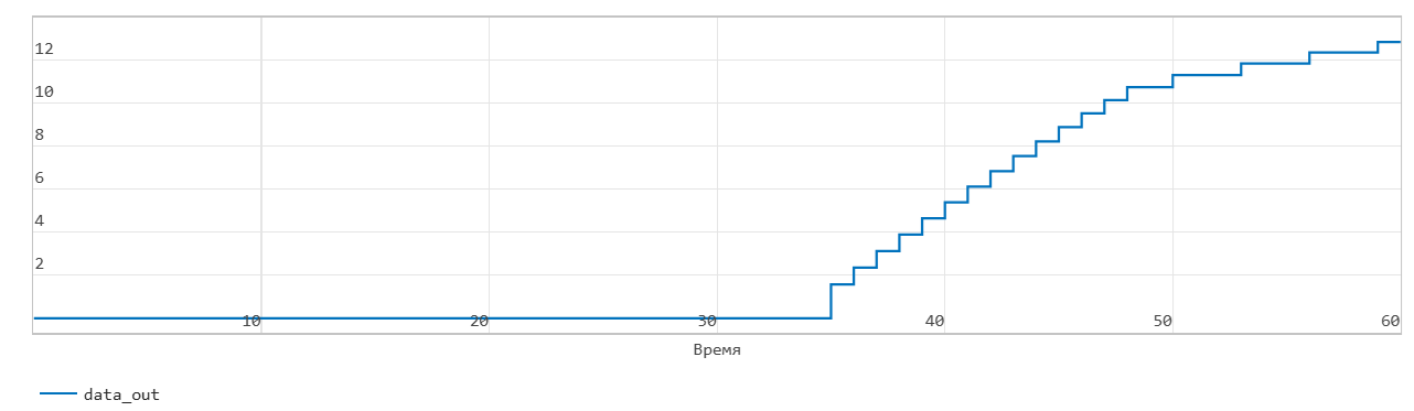
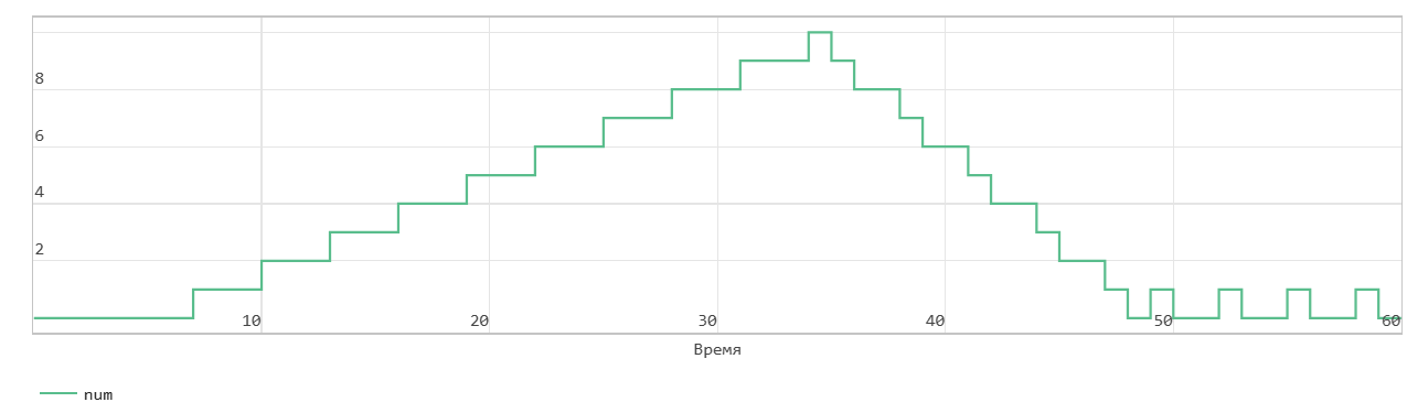
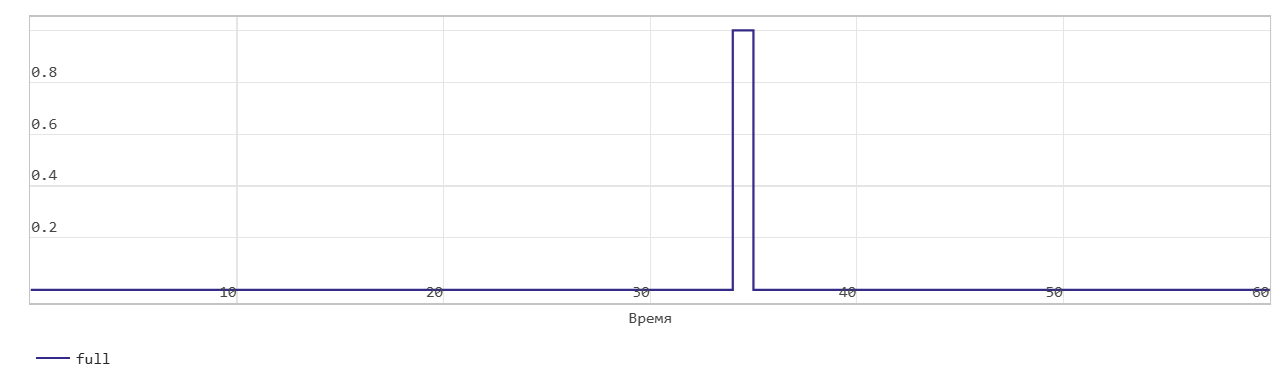
The figure shows that when the read_en signal is 1 at time step 34, the dout signal outputs the oldest record in the FIFO at the next time step 35. The Full flag is cleared, the Num signal decreases by 1 starting at time step 35 as data is read from the FIFO.
When the Num signal becomes 0, the Empty signal is asserted. After the Empty signal becomes 0, if you read more data from the FIFO, the block generates a warning.
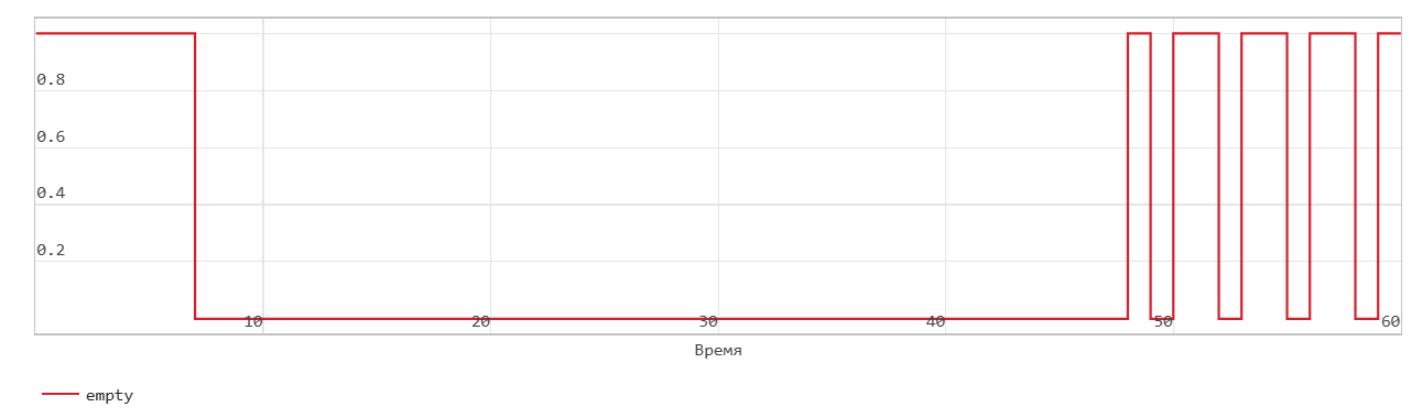
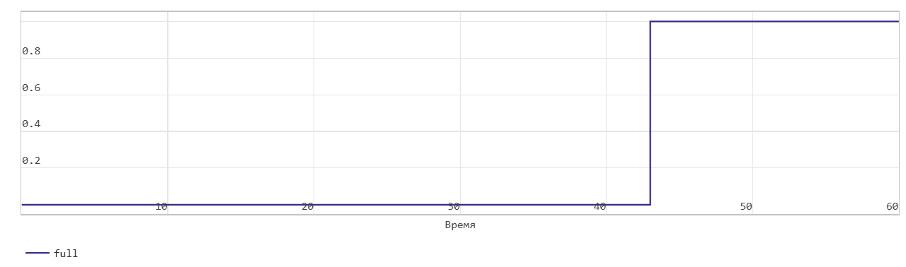
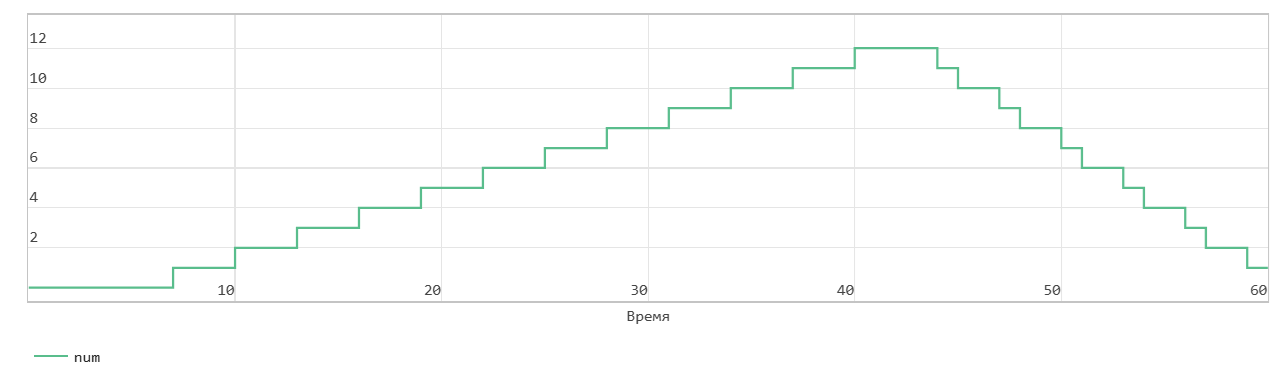
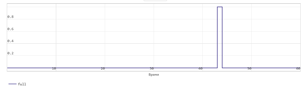
First word write operation through FIFO
This figure shows the write operation when the Mode parameters are set to FWFT. The Push input port acts as an enable signal for the write operation. In the figure, write_en denotes this signal.


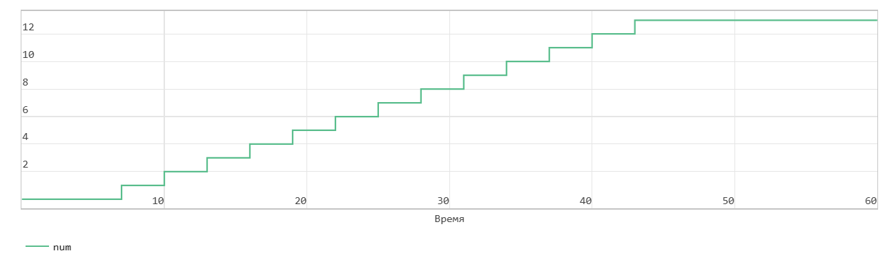
When the write_en signal is 0, the block does not write data to the FIFO and sets the Empty flag.
When the write_en signal becomes 1, the block transfers the value of the din signal on the In input port to the end of the FIFO register in the next time step. The Num signal indicates the amount of data in the FIFO register. Each time you write data to the FIFO, the Num signal is incremented by 1. At time step 6, write_en is equal to 1. At the next time step 7, the data is written to the FIFO. The Num signal is incremented by 1 and the Empty flag is cancelled.
The FIFO uses the register size specified by the Register size parameters. By default, the register size is 10. In the figure, when the Num signal becomes equal to 13 at time step 43, the Full signal is asserted. In FWFT mode, the FIFO can store another 3 values beyond its specified size. After the Full signal becomes 1, if you write more data to the FIFO, the block generates a warning.
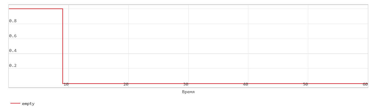
Read operation from FIFO with first word transition
This figure shows a read operation when the Mode parameters are set to FWFT. The Pop input port acts as an enable signal for the read operation. In the figure, read_en denotes this signal.
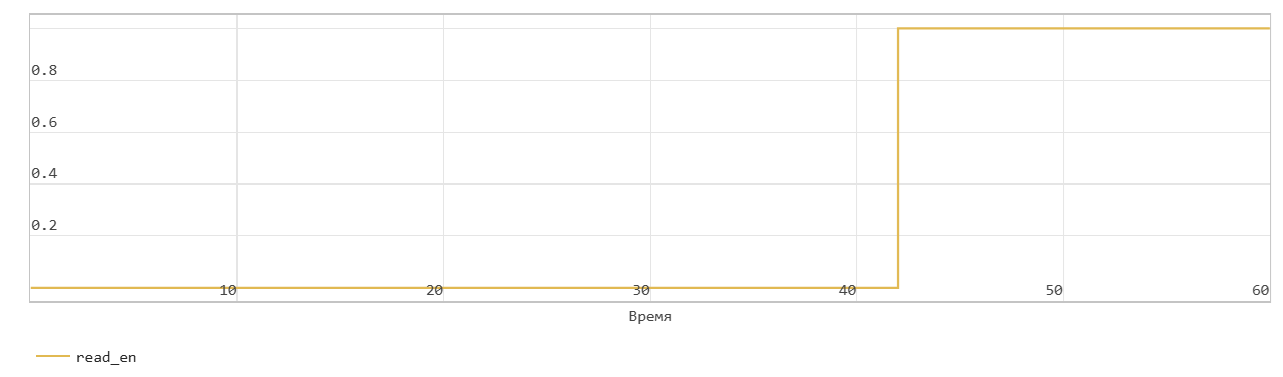
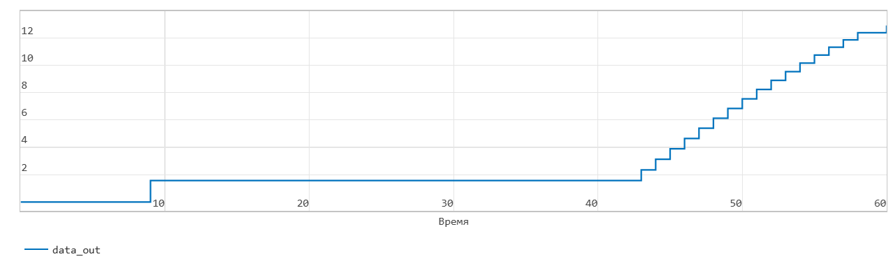
In FWFT mode, the first value you write to the FIFO goes to the Out output signal.
In the figure, read_en becomes 1 at time step 42, the FIFO reads the first value of the data out signal at time step 9. You can use this to look ahead and see the data that was first written to the FIFO.
When the Num signal becomes 0, the Empty signal is asserted. After the Empty signal becomes 0, if you read more data from the FIFO, the block generates a warning.