{blockLibraryPPblocksPPFFPhysicalSSModelingFFElectricalFFPassiveFFPotentiometerPPlabel} (Electrical Passive)
A rotary or linear potentiometer controlled by an external signal.
blockType: AcausalElectricPowerSystems.Passive.Potentiometer
|
Path in the library: |

Description
Block Potentiometer It is a potentiometer with a rotary or linear stroke and a movable contact, which is controlled by an input signal.
If the resistance of the potentiometer varies linearly depending on the position of its rod, then the resistance between the position of the rod and the port L is:
,
where
-
— resistance between the position of the movable contact and the port L;
-
— total resistance between ports L and R;
-
— position of the movable contact;
-
— the value of the input signal at which the movable contact is located at the port L;
-
— the value of the input signal at which the movable contact is located at port R;
-
— residual resistance. This is the resistance between the movable contact and the L port when equally . It is also the resistance between the movable contact and the port. When equally .
If the parameter Taper of the potentiometer resistance is specified Logarithmic, then the resistance between the position of the movable contact and the port L will be:
,
where and selected so that in this and in is equal to the resistance Resistance when centered when the movable contact is in the center.
| Potentiometers, which are often referred to as LOG potentiometers, or log-taper potentiometers, actually have an exponential taper. That is, the resistance gradient between the movable contact and the left port increases as the resistance increases. Block Potentiometer implements exactly this behavior. |
For linear and logarithmic potentiometers, the resistance between the position of the movable contact and the port R is:
,
where
-
— resistance between the movable contact and the port R;
-
— total resistance between ports L and R;
-
— resistance between the movable contact and the L port.
Ports
Entrance
x — position control of the movable contact
scalar
The port of the input signal controlling the position of the movable contact.
Non-directional
L — left contact
electricity
The electrical port connected to the left contact of the potentiometer.
R — right contact
electricity
The electrical port connected to the right contact of the potentiometer.
Dependencies
To use this port, set the Number of visible ports parameter to Three: left, right, and wiper.
W — movable contact
electricity
An electrical port connected by a movable contact of the potentiometer.
Parameters
Number of visible ports — option for displaying ports
Three: left, right, and wiper (default) | Two: left and wiper
Selecting the option to turn on the right port of the potentiometer, R.
Total resistance — Total pass resistance:q[<br>] 1000.0 ohms (default)
To use this parameter, set the Number of visible ports parameter to Three: left, right, and wiper.
Residual resistance — residual resistance
1.0 Ohm (default) | positive scalar
The resistance measured between the movable contact and the nearest port (L or R) when the movable contact is close to this port. This parameter can be used to indicate the inability of the movable contact to reach the end of the track due to a mechanical stop. This value must be greater than or equal to zero. The typical value is in 5000 times less than the total resistance.
Dependencies
To use this parameter, set the Number of visible ports parameter to Three: left, right, and wiper.
CControl input for wiper at L port — the value of the input signal for moving the movable contact to the L pass port:q[<br>] 0.0 (default)
The value of the input signal on port x, corresponding to the movable pin located close to port L.
Dependencies
To use this parameter, set the Number of visible ports parameter to Three: left, right, and wiper.
Control input for wiper at R port — the value of the input signal for moving the movable contact to the R pass port:q[<br>] 1.0 (default)
The value of the input signal on port x, corresponding to the movable pin located close to port R.
Dependencies
To use this parameter, set the Number of visible ports parameter to Three: left, right, and wiper.
Minimum resistance — minimum pass resistance:q[<br>] 1.0 Ohm (default)
The minimum allowable resistance measured between the movable contact and the left port L when the movable contact is located at the left port. The value of this parameter should be higher. 0 and less than the value of the Maximum resistance parameter.
Dependencies
To use this parameter, set the Number of visible ports parameter to Two: left and wiper.
Maximum resistance — maximum pass resistance:q[<br>] 999.0 Ohms (default)
The maximum allowable resistance measured between the movable contact and the left port L when the movable contact is located at the left port. The value of this parameter should be higher. 0 and more than the value of the Minimum resistance parameter.
Dependencies
To use this parameter, set the Number of visible ports parameter to Two: left and wiper.
Control input for wiper at minimum resistance — the value of the input signal for moving the movable contact to the position with minimum resistance
0.0 (default)
The value of the input signal on port x, corresponding to the movable pin located at port L.
Dependencies
To use this parameter, set the Number of visible ports parameter to Two: left and wiper.
Control input for wiper at maximum resistance — the value of the input signal for moving the movable contact to the position with maximum resistance
1.0 (default)
The value of the input signal at port x, corresponding to the movable pin located at the furthest position from port L. The default value is 0.
Dependencies
To use this parameter, set the Number of visible ports parameter to Two: left and wiper.
Taper — type of pass resistance scale:q[<br>] Linear (by default) | Logarithmic
The resistance scale of the potentiometer.
Parameters Linear and Logarithmic they don’t model the same scale. A block with linear parameterization cannot be used to simulate a logarithmic potentiometer, since the logarithmic scale is nonlinear.
|
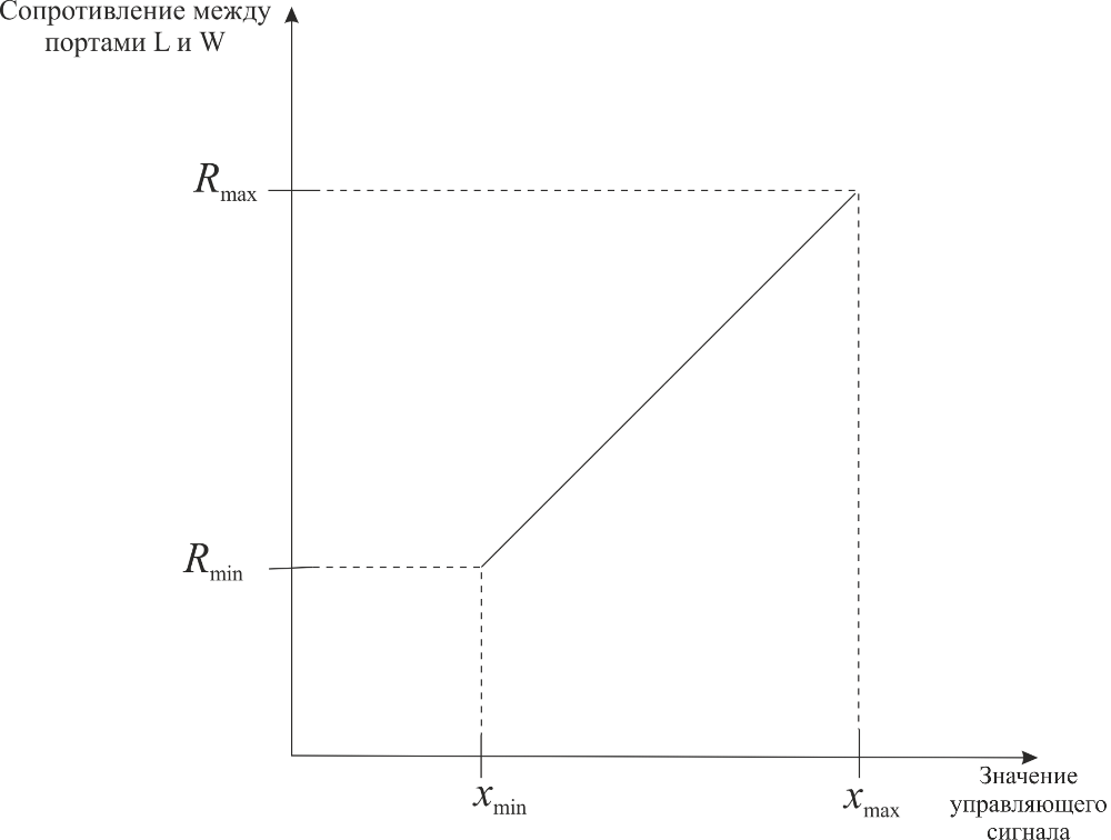
For the parameter Linear, the relationship between the input signal value and the resistance between ports L and W has the form:
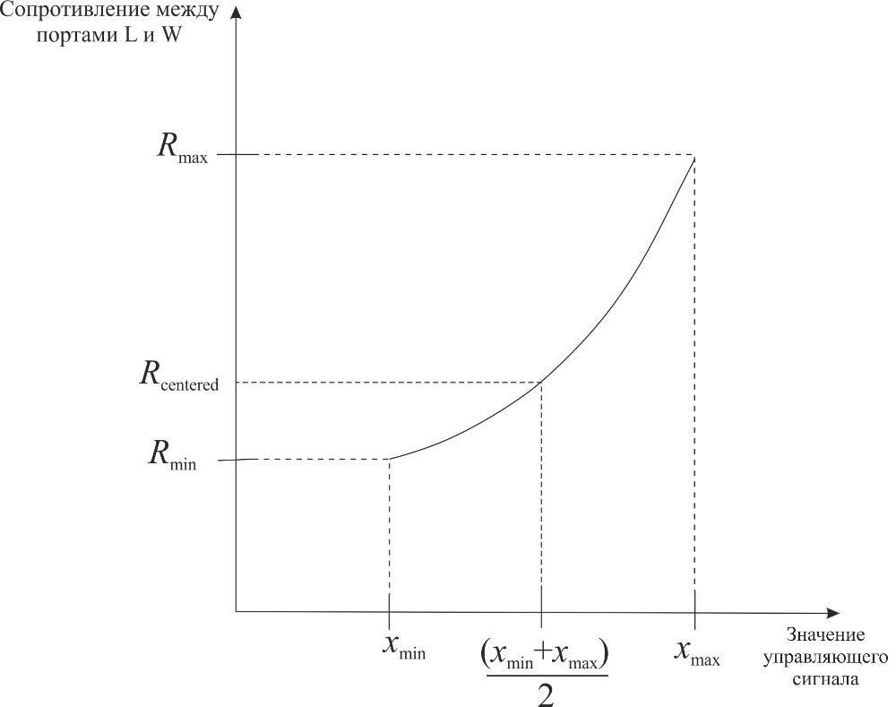
For the parameter Logarithmic, the relationship between the input signal value and the resistance between ports L and W has the form:
Resistance when centered — resistance in the center of the
200.0 Ohms (default)
If you have set the Resistance gradient parameter to Higher at L, then this parameter represents the resistance between port L and port W when the movable contact is centered. Otherwise, if the Resistance gradient parameter is set to Higher at R, then this parameter represents the resistance between ports R and W when the movable contact is centered. Since the resistance scale has an exponential shape, the value of the Resistance when centered parameter must be less than half of the value of the Total resistance parameter.
Dependencies
To use this parameter, set the Taper parameter to Logarithmic.
Resistance gradient — type of resistance gradient
Higher at R (default) | Higher at L
Determines on which side the resistance of the potentiometer changes more sharply depending on the input signal (the magnitude of the gradient) - on the left or on the right.
Dependencies
To use this parameter, set the Taper parameter to Logarithmic.