Supercapacitor
Electrochemical double layer capacitor.
blockType: AcausalElectricPowerSystems.Passive.Supercapacitor
|
Path in the library: |

Description
The Supercapacitor unit is an electrochemical double layer capacitor (ELDC), commonly referred to as a supercapacitor or ultracapacitor. The capacitance values of supercapacitors are orders of magnitude greater than those of conventional capacitors. Supercapacitors can provide bursts of energy because they are able to charge and discharge rapidly.
You can model any number of supercapacitors connected in series or parallel using a single block Supercapacitor. To do this, set the parameters Number of series cells or Number of parallel cells to a value greater than 1. The block only models the equations for a single supercapacitor cell, but it does calculate:
-
Output voltage as a function of the number of cells connected in series;
-
Current depending on the number of cells connected in parallel.
Calculating the output of a multi-cell supercapacitor based on the output for a single cell is more efficient than modelling the equations for each cell separately.
The figure shows the equivalent circuit for a single cell in a supercapacitor block. This circuit is a network of resistors and capacitors that is commonly used to model the behaviour of a supercapacitor.
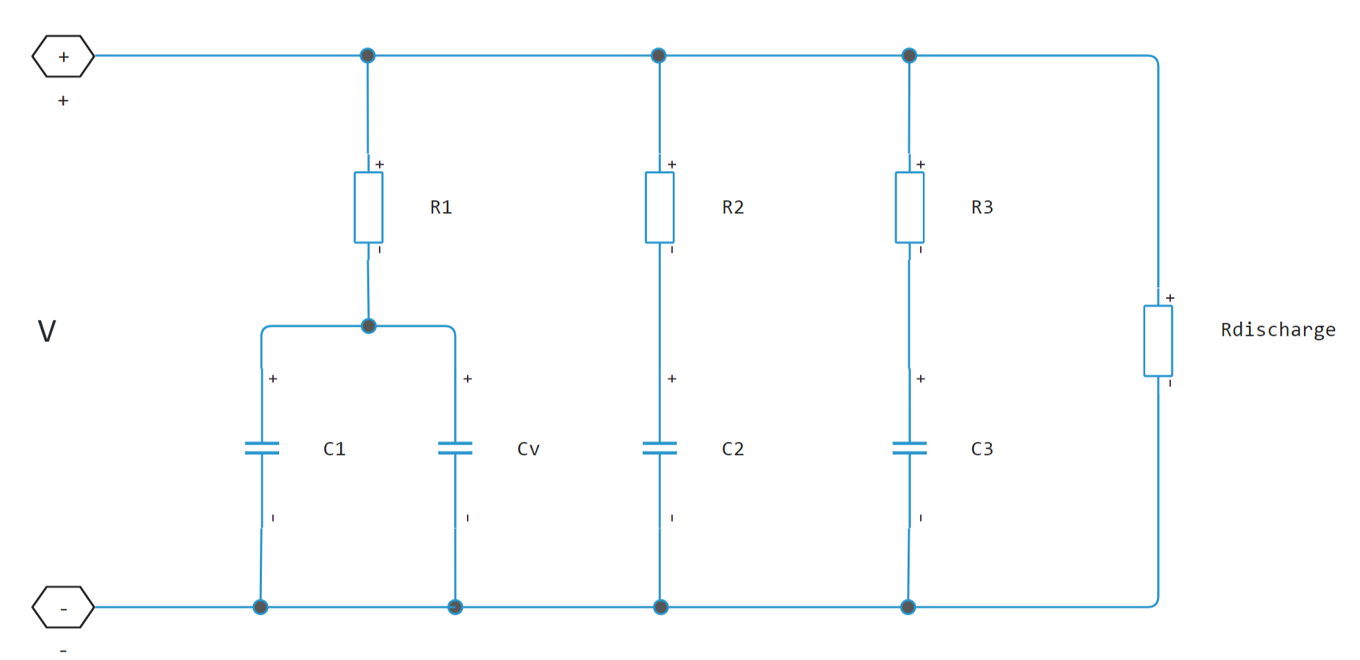
The capacitors , and have fixed capacitance. The capacitance of the capacitor depends on the capacitor voltage. The resistors , , and have fixed resistances. The voltage across each individual fixed capacitor in the supercapacitor block is calculated as
where
-
- block voltage;
-
- number of cells connected in series;
-
- branch number. = [1, 2, 3];
-
- current through -th branch;
-
- resistance in -th branch;
-
- voltage across the capacitor in -th branch.
The equation for the current through the first branch of the supercapacitor depends on the voltage across the capacitors in that branch. If the voltage on the capacitors is positive, i.e.
afterwards
or
where
-
- is the voltage across the capacitors in the first branch;
-
- is the capacitance of the fixed capacitor in the first branch;
-
- is the voltage-dependent capacitance gain;
-
- is the current through the first branch.
For the other branches, the current is determined as follows:
where
-
- branch number. =[2, 3];
-
- capacity of -th branch.
The total current through the supercapacitor block is:
where
-
- is the number of parallel connected cells;
-
- is the self-discharge resistance of the supercapacitor;
-
- current through the supercapacitor.
Parameters
Cell Characteristics
Fixed resistances, [R1 R2 R3] - fixed resistances for each branch
[0.2, 90.0, 1000.0] Ohm (by default) | array
Specify the resistances for the constant resistance resistors in the individual branches of the supercapacitor as an array.
Fixed capacitances, [C1 C2 C3] - fixed capacitance values for each branch
[2.5, 1.5, 4.0] F (by default) | array
Specify the individual capacitance values for constant capacitance capacitors in the supercapacitor as an array.
Voltage-dependent capacitor gain - variable capacitance factor for the first branch
0.95 F/V (by default) | scalar
Specify the variable capacitance factor, , for the voltage-dependent capacitor in the first branch of the supercapacitor. For information on determining the variable capacitance factor, see 1.
Self-discharge resistance - self-discharge resistance
`inf (by default)
Specify the self-discharge resistance of a supercapacitor connected between two terminals.
Configuration
Number of series cells - number of series connected cells of the supercapacitor
1 (By default) | scalar
Specify the number of cells in the supercapacitor connected in series.
Number of parallel cells - number of parallel cells in the supercapacitor
1 (By default) | scalar.
Specify the number of supercapacitor cells connected in parallel.
Initial Targets
Current
Priority - Priority
None (by default) | Higt | Low
Current priority.
Value - current value
0.0 A (By default) | scalar
Current value.
The unit of measurement is A.
Voltage
Priority - priority
None (by default) | Higt | Low
Voltage priority.
Value - voltage value
0.0 V (by default) | scalar
Voltage value.
The unit of measurement is V.
Per-cell voltage across C1
Priority - priority
Higt (by default) | None | Low
Cell voltage across capacitor .
Value - value of voltage on the cell through capacitor C1
0.0 V (by default) | scalar
Voltage value on the cell through capacitor .
The unit of measurement is V.
References
-
Zubieta, L. and R. Bonert. "Characterisation of Double-Layer Capacitors for Power Electronics Applications." IEEE Transactions on Industry Applications, Vol. 36, No. 1, 2000, pp. 199-205.
-
Weddell, A. S., G. V. Merrett, T. J. Kazmierski, and B. M. Al-Hashimi. "Accurate Supercapacitor Modeling for Energy-Harvesting Wireless Sensor Nodes." IEEE Transactions on Circuits And Systems-II: Express Briefs, Vol. 58, No. 12, 2011, pp. 911-915.