Varistor
A voltage-dependent resistor model.
blockType: AcausalElectricPowerSystems.Passive.Varistor
|
Path in the library: |

Description
Block Varistor It is a voltage-dependent resistor (VDR). This component is also commonly known as a metal oxide varistor (MOV). The unit has high resistance at low voltages and low resistance at high voltages.
You can protect parts of an electrical circuit from power surges by placing this unit in parallel with them. When a voltage surge occurs, the resistance of the varistor drops significantly, resulting in current flowing through the varistor rather than through the circuit.
Use the Parameterization parameter to select one of the two behaviors for this block. Option Linear It is based on the on and off states of the varistor and uses a linear relationship between current and voltage in both areas. Option Power-law uses the exponential relationship between current and voltage in the initial switching state. This option also adds a third, linear area at higher voltages.
Linear parameterization
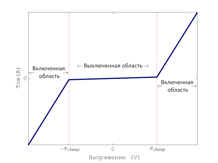
This parameterization option divides the voltage-current dependence into two linear regions.:
-
Off area — The resistance is high and the current increases slowly with increasing voltage.
-
Switched area — The resistance is low and the current increases rapidly with increasing voltage.
This figure shows the dependence of voltage on current in the on and off areas.
Use linear parameterization in one of these scenarios.:
-
You are simulating voltage surges near a threshold voltage.
-
You expect your varistor to behave linearly in all areas.
The dependence of voltage on current for a linear varistor has the form:
,
where
-
and — voltage and current of the varistor, respectively;
-
— the threshold voltage separating the two areas of operation. Set this value using the Clamping voltage parameter;
-
and — resistance in the on and off areas. Set these values using the On resistance and Off resistance parameters, respectively.;
-
— a constant used to ensure continuity of current between two areas:
.
Parameterization according to the law of power
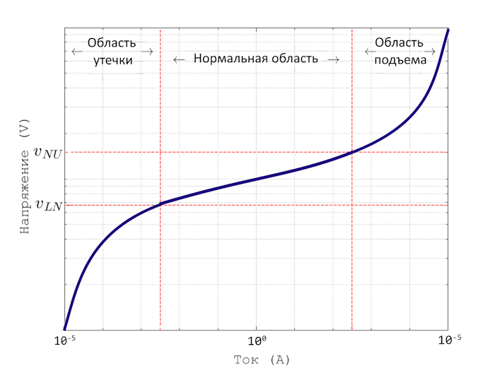
This parameterization option divides the voltage-current dependence into three areas:
-
Leakage area — The resistance is high, and the current increases slowly with increasing voltage.
-
Normal range — Resistance decreases exponentially with increasing voltage.
-
Lifting area — the resistance is low, the current increases rapidly with increasing voltage.
This figure shows three areas of work on a logarithmic scale.
Use power law parameterization in one of these scenarios.:
-
You are simulating power surges over a large voltage range.
-
You expect your varistor to behave exponentially in the first turn-on region.
The dependence of voltage on current for a varistor according to the power law has the form:
,
where
-
and — voltage and current of the varistor, respectively;
-
— the exponent of the power law, which determines the rate of increase in current with increasing voltage in normal operation. Set this value using the Normal-mode power-law exponent parameter;
-
and — threshold voltages corresponding to the transition points leakage — normal mode and normal mode — rise. Set these values using the Leakage to normal voltage transition and Normal to upturn voltage transition parameters, respectively;
-
and — resistance in the areas of leakage and lifting. Set these values using the Leakage-mode resistance and Upturn-mode resistance parameters, respectively.
-
, and — constants used to ensure continuity of current between areas:
,
,
and
.
Parameters
Main
Parameterization — operation mode of the varistor
Linear (by default) | Power-law
Select how the resistance of the varistor changes with increasing voltage:
-
Linear— two areas. The low voltage area has a high resistance, and the high voltage area has a low resistance. -
Power-law— three areas. The leakage area has a high resistance. The normal region has exponentially decreasing resistance. The lifting area has low resistance.
Clamping voltage — threshold voltage
260 V (default) | a positive number
Transition point voltage, , between the off and on states of the linear varistor.
Dependencies
Used if the Parameterization parameter is set to Linear.
Off resistance — resistance of the off pass area:q[<br>] 3e8 ohms (default) | a positive number
Low voltage resistance, , the varistor is switched off.
Dependencies
Used if the Parameterization parameter is set to Linear.
On resistance — resistance of the enabled pass area:q[<br>] 1 Ohm (default) | a positive number
High voltage resistance, , the varistor is switched on.
Dependencies
Used if the Parameterization parameter is set to Linear.
Leakage to normal voltage transition — first threshold voltage
130 V (default) | a positive number
Transition point voltage, , between the leakage area and the normal area of the varistor with the power law.
Dependencies
Used if the Parameterization parameter is set to Power-law.
Normal to upturn voltage transition — second threshold voltage
300 V (default) | a positive number
Transition point voltage, , between the normal region and the rise region of the varistor with the power law.
Dependencies
Used if the Parameterization parameter is set to Power-law.
Leakage-mode resistance — resistance in the area of leakage
3e8 ohms (default) | a positive number
Low voltage resistance, , varistor in the leakage area.
Dependencies
Used if the Parameterization parameter is set to Power-law.
Normal-mode power-law exponent — resistance in the normal pass range:q[<br>] 45 (default) | a positive number
The exponent that determines the rate of increase in current when the voltage across the varistor increases in the normal range.
Dependencies
Used if the Parameterization parameter is set to Power-law.
Upturn-mode resistance — resistance in the lifting area of the
0.07 ohms (default) | a positive number
High voltage resistance, , varistor in the lifting area.
Dependencies
Used if the Parameterization parameter is set to Power-law.
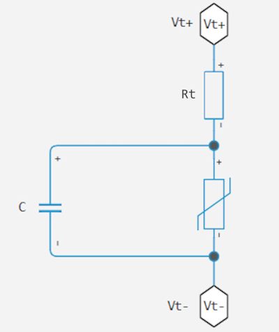
Terminal resistance — pass terminal resistance:q[<br>] 100e-6 ohms (default) | a non-negative number
A small constant resistance in series with the varistor. Set this value to zero to remove the resistance from the equivalent circuit.
Capacity — parallel capacity of
4.4 nF (default) | a non-negative number
The parasitic capacitance is parallel to the varistor. Set this value to zero to remove the capacitor from the equivalent circuit.