Diode (Advanced)
|
Page in progress. |
Diode with a piecewise linear, exponential or tabulated VAC.
blockType: AcausalElectricPowerSystems.Semiconductors.Diode
|
Path in the library: |

Description
A Diode block can represent a diode with a piecewise linear, exponential or tabulated - curve (volt-ampere characteristic, VAC).
Diode with piecewise linear VAC
If the forward voltage of the diode exceeds the value specified in Forward voltage, the diode behaves as a linear resistor with resistance specified in On resistance. Otherwise, the diode behaves as a linear resistor with the small conductance specified in Off conductance. At zero voltage, zero current flows through the diode.
Diode with exponential VAC
The exponential EAC is the following relationship between diode current and diode voltage :
, at
at
where:
-
- electron’s elementary charge (1.602176e-19 Cl).
-
- Boltzmann constant (1.3806503e-23 J/K).
-
- value of the Reverse breakdown voltage parameter.
-
- emission coefficient.
-
- saturation current.
-
- is the temperature at which the diode parameters are set, determined by the value of the Measurement temperature parameter.
When , the block replaces to , which corresponds to the diode current gradient at and extrapolates linearly.
When , the block replaces to , which also corresponds to the gradient and is extrapolated linearly.
Conventional electrical circuits do not reach these extremes. The block provides this linear extrapolation to facilitate convergence when solving constraints during the modelling process.
If Use parameters IS and N are selected for the Parameterization parameter, the diode is specified as parameters Saturation current IS and Emission coefficient N.
If Use two I-V curve data points is selected for the parameter parameterization, then two voltage and current measurement points on the diode VAC are set, and the block determines the values and . It calculates and as follows:
-
-
Where:
-
.
-
and are the values of the parameter Voltages [V1 V2].
-
and - values of parameter Currents [I1 I2].
-
If Use an I-V data point and IS is selected for the Parameterization parameter, the unit calculates as follows:
If Use an I-V data point and N is selected for the Parameterization parameter, the block calculates as follows:
Diode with tabulated VAC
To model a diode with a tabulated BAC, set the Diode model parameter to Tabulated I-V curve. This figure shows the implementation of a diode variant with tabulated I-V curve:
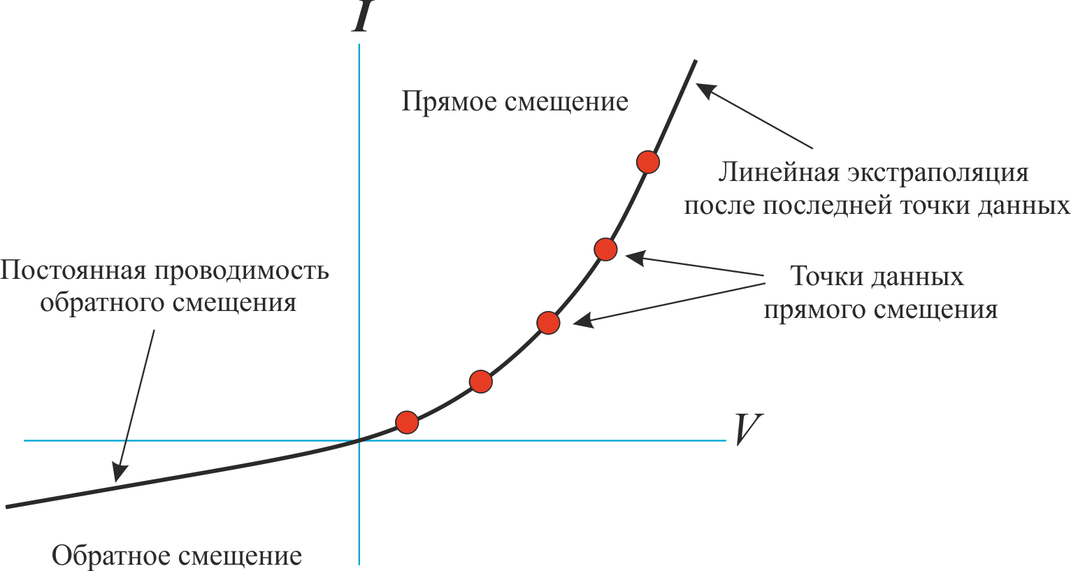
You only provide tabulated data for forward bias. The block uses modified Akim interpolation to find intermediate values. If the voltage or current is outside the range of the tabular data, the block uses linear extrapolation after the last voltage and current data point.
For reverse bias:
-
If the voltage is less than −1 V, the block simulates a VAC with a constant off conductance equal to the value of the Off conductance parameter. The setpoint must be less than the gradient of the forward VAC for small positive voltages.
-
If the voltage is between −1 and 0 V, the block uses a modified Akim interpolation so that the forward and reverse bias VACs overlap smoothly.
|
No reverse breakdown is modelled for a diode with a tabulated BAC. |
Transition capacitance
There are three ways to enable the modelling of the junction capacitance:
-
Select the value
Include fixed or zero junction capacitancefor the parameter parameterization. In this case the capacitance is fixed. -
Select the value
Use parameters CJ0, VJ, M & FCfor the Parameterization parameter. In this case the block uses the coefficients , , and to calculate the junction capacitance which depends on the transient voltage. -
Select
Use C-V curve data pointsfor parameterization. In this case, the block uses the three C-V curve capacitance values to estimate , and and, using these values together with the set value , calculates the junction capacitance that depends on the junction voltage. The block calculates , , as follows:
Where:
-
- Reverse bias voltages [VR1 VR2 VR3] parameter values.
-
- parameter values Corresponding capacitances [C1 C2 C3].
The reverse bias voltages (defined as positive values) must satisfy the condition . This means that the capacitances must satisfy the condition , since reverse bias expands the depletion region and therefore reduces the capacitance. Violation of these inequalities leads to an error. The voltages and must be sufficiently distant from the transition potential . The voltage must be less than the junction potential , with the typical value of being `0.1V.
The voltage-dependent junction capacitance is defined in terms of capacitor charge accumulation as:
-
For :
-
For :
Where:
Charge dynamics
For applications such as switching diodes, it can be important to model the charge dynamics of the diode. When a reverse voltage is applied to a direct-input diode, it takes time for the charge to dissipate and hence for the diode to switch off. The time required to switch off the diode is mainly determined by the span time parameter. After switching off the diode, the remaining charge is dissipated, the rate of this process being determined by the carrier lifetime.
To account for these effects, the Diode block uses the model of Lauritzen and Ma. Here are the defining equations:
(1)
(2)
(3)
Where:
-
- diode current.
-
- junction charge.
-
- total accumulated charge.
-
- travelling time.
-
- carrier lifetime.
-
- diode voltage.
-
- diode forward voltage.
-
- diode switch-on resistance.
-
- conductivity of the diode in the switched-off state.
This graph shows a typical reverse current characteristic for a diode.
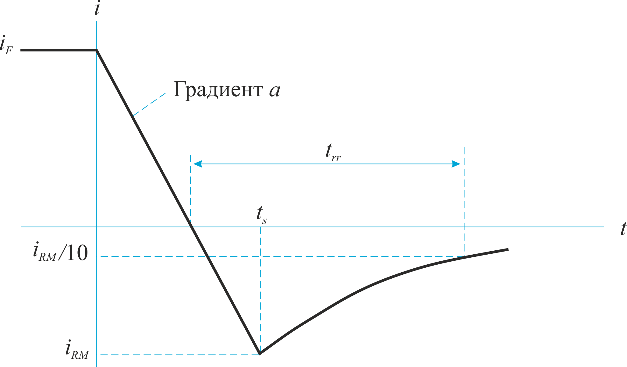
Where:
-
- peak reverse current.
-
- initial forward current during measurement .
-
- rate of change of current during measurement .
-
- is the reverse recovery time.
The diode data sheets provide peak reverse current values for the initial forward current and the constant rate of change of current. The data sheet may also provide values for the reverse recovery time and full recovery charge.
How the block calculates and
The block calculates the span time, , and carrier lifetime, , based on the values entered for the Charge Dynamics parameter. The block uses and to solve the charge dynamics equations 1, 2, and 3.
During the initial current decay in the reverse mode, the diode remains on and the rate of current change is determined by an external test circuit.
The block first uses equation 1 to perform this calculation.
(4)
Then it substitutes equation 4 into equation 2.
(5)
Equation 5 is then solved for ,
(6)
where is a constant value.
When , and , since the system is in steady state.
Substituting these relations into Equation 6 and solving it, we obtain .
Thus,
(7)
At time , the current is , and the junction charge is zero. The block substitutes these values into Equation 1.
(8)
The block expresses from Equation 8 and substitutes the result into Equation 7.
(9)
The block then expresses the time through , and .
(10)
Consider the diode recovery process, i.e., when . The diode is reverse biased and the junction current and charge are effectively zero.
The current is determined by Eq:
, (11)
where:
(12)
The block now relates the expression in Equation 12 to the backward recovery time .
When current is .
Therefore
(13)
and
(14).
The block uses Equations 9 and 14 to calculate the values of and . The calculation uses an iterative scheme because there is an exponential term in Equation 9.
Alternatives to direct specification
In addition to allowing the block to specify the reverse recovery time directly, it supports three alternative parameterisations. The block can define from any of the parameters:
-
Back recovery time stretch factor .
-
Reverse recovery charge , if the specification specifies this value instead of the reverse recovery time.
-
Reverse recovery energy , if the specification specifies this value instead of the reverse recovery time.
The relationship between the recovery time stretch factor and is expressed by the equation
The reverse recovery time should be greater than . Its typical value is .
Therefore, the typical value of is 3. must be greater than 1.
The reverse recovery charge is the integral over the reverse current time from the moment the current goes negative until it falls back to zero.
The initial charge by time is expressed by the following equation:
(15).
Integration of Equation 11 gives the charge between the time instants and inf. This charge is equal to
.
Thus, the total charge of the reverse reduction is determined by Eq.
. (16).
Rearranging equation 16 to solve and substituting the result into equation 14 gives an equation expressing in terms of :
.
Alternatively, the block calculates , using the reverse recovery energy . This equation determines the voltage curve across the diode:
, (17).
where is the maximum reverse voltage of the diode.
If , which is the usual condition for a reverse recovery check circuit, the block calculates the maximum reverse voltage of the diode as:
.
Since the value of the decay time is small, the block assumes that the diode current decay is linear:
. (18).
Equation 18 is then substituted into Equation 5:
. (19).
To obtain the total accumulated charge, equation 19 is solved :
, (20),
where is the current gradient.
When , the peak reverse current is:
. (21).
The block now substitutes equation 21 into equation 20:
. (22)
Finally, the block solves Equation 22 to obtain the reverse recovery energy:
. (23)
Charge dynamics
When charge dynamics modelling is enabled, the Diode block calculates the charge at the transition as follows
,
where:
-
- diode current without considering the charge model.
-
- transition charge.
-
- transit time.
-
- carrier lifetime.
This equation then determines the value of the diode current:
Where:
-
- current in the diode.
-
- is the total stored charge.
-
- is the current value of the charge coefficient.
Temperature dependence
By default, no temperature dependence is modelled for the Diode block, and the device is modelled at the temperature for which the block parameters are set. Diode with exponential VAC contains several options for modelling the temperature dependence of diode current and voltage during simulation. The temperature dependence of the junction capacitance is not modelled because its influence is much smaller.
When the temperature dependence is included, the diode’s defining equation remains the same. The value of the measurement temperature, , is replaced by the modelling temperature, . The saturation current, , becomes a function of temperature according to the following equation:
,
where:
-
- is the temperature at which the diode parameters are set, determined by the value of the Measurement temperature parameter.
-
- modelling temperature.
-
- is the saturation current at the measurement temperature.
-
- saturation current at the simulation temperature. This saturation current value is used in the standard diode equation when the temperature dependence is modelled.
-
- the energy gap for this type of semiconductor, measured in joules (J). For silicon, a value of
1.11 eVis usually assumed, where1 eVis equal to1.602e-19 J. -
- temperature exponent of the saturation current. For pn junction diodes, this value is usually
3.0, and for Schottky barrier diodes, it is usually2.0. -
- emission coefficient.
-
- Boltzmann constant (1.3806503e-23 J/K).
The respective values of and depend on the type of diode and the semiconductor material used. By default values for specific material types and diodes reflect approximate behaviour with temperature changes. By default values for common diode types are given in the block.
In practice, to simulate the exact behaviour of a particular diode requires adjusting the values and . Some manufacturers specify these adjusted values in the data sheets, where you can view the corresponding values. Otherwise, you can determine improved estimates for , using a specific current-voltage data point at a higher temperature in the data sheet. For this purpose, the block includes a parameterization option. It also allows the saturation current at higher temperature to be set directly .
| The temperature behaviour of the device also depends on the emission factor. An incorrect value for the emission factor can give an incorrect temperature dependence because the saturation current depends on the ratio of and . |
If the final reverse breakdown voltage , is set, the value of the reverse is modulated by the reverse breakdown temperature coefficient (set with the parameter Reverse breakdown voltage temperature coefficient, dBV/dT):
(24).
Assumptions and limitations
-
When selecting
Use two I-V curve data pointsfor the Parameterization parameter, select a pair of voltages close to the diode turn-on voltage. Typically, this voltage is in the range of 0.05 to 1 V. Using values outside this range can cause problems with the numbers and poor estimates for and . -
The block does not take into account the effect of temperature on junction capacitance.
-
It may be necessary to use non-zero values for the ohmic resistance and junction capacitance to avoid problems in numerical modelling, but the simulation may run faster if these values are set to zero.
-
The `Tabulated I-V curve' mode cannot be used for back breakdown modelling.
Parameters
Basic
Diode model - diode model
Piecewise Linear (by default) | Exponential | Tabulated I-V curve
-
Piecewise Linear- modelling of diode with piecewise linear VAC as described in the section Diode with piecewise linear VAC. This is the method used by default. -
Exponential- diode modelling with exponential VAC, as described in section . Diode with exponential VAC. -
Tabulated I-V curve- modelling a diode with tabulated values - with forward bias plus fixed conductance at reverse bias off, as described in section Diode with tabulated VAC.
Table type - tabulated function
Table in If(Tj,Vf) form (by default) | Table in Vf(Tj,If) form
Whether to tabulate current as a function of temperature and voltage or voltage as a function of temperature and current.
Dependencies
To use this parameter, set the Diode model parameter to Tabulated I-V curve.
Forward voltage - forward voltage
0.6 V (by default).
The minimum voltage that must be applied to the diode for it to go into the forward mode.
Dependencies
To use this parameter, set the Diode model parameter to Piecewise linear.
On resistance - On resistance
0.3 ohms (by default).
Diode resistance at forward bias.
Dependencies
To use this parameter, set the Diode model parameter to Piecewise linear.
Off conductance - disabled conductance
1e-8 1/ohm (by default).
The conductance of the diode when it is reverse biased.
Dependencies
To use this parameter, set the Diode model parameter to Piecewise linear or Tabulated I-V curve.
parameterization - parameterization of the model
Use two I-V curve data points (by default) | Use parameters IS and N | Use an I-V data point and IS | Use an I-V data point and N.
Select one of the following methods of model parameterization:
-
Use two I-V curve data points- set the measured data at two VAC points of the diode. This method is used by default. -
Use parameters IS and N- specify saturation current and emission factor. -
Use an I-V data point and IS- specify the measured data at one VAC point of the diode in combination with the saturation current. -
Use an I-V data point and N- specify the measured data at one point of the diode VAC in combination with the emission factor.
Dependencies
To use this parameter, set the Diode model parameter to Exponential.
Currents [I1 I2] is a vector of current values at two points
[0.0137, 0.545] A (by default).
Vector of current values in two points of diode VAC, which the block uses for calculation and .
Dependencies
To use this parameter, set Diode model to Exponential and parameterization to Use two I-V curve data points.
Voltages [V1 V2] - vector of voltage values at two points
[0.6, 0.7] V (by default).
Vector of voltage values in two points of diode VAC, which the block uses for calculation and .
Dependencies
To use this parameter, set the Diode model parameter to Exponential and the Parameterization parameter to Use two I-V curve data points.
Saturation current, IS - saturation current
1e-12 A (By default).
The amount of current to which the ideal diode equation approaches asymptotically for very large reverse bias levels.
Dependencies
To use this parameter, set the Diode model parameter to Exponential and the Parameterization parameter to Use parameters IS and N or Use an I-V data point and IS.
Emission coefficient, N - emission coefficient of the diode
1 (By default).
Diode emission coefficient or ideality coefficient.
Dependencies
To use this parameter, set Diode model to Exponential and parameterization to Use parameters IS and N or Use an I-V data point and IS.
Current I1 - current value
0.0137 A (By default).
The value of current at the point on the diode VAC, which the block uses for calculations. Depending on the value of the Parameterization parameter, the block uses this parameter to calculate or .
Dependencies
To use this parameter, set the Diode model parameter to Exponential and the Parameterization parameter to Use an I-V data point and IS or Use an I-V data point and N.
Voltage V1 - voltage value
0.6 V (by default).
The voltage value at the point at - of the diode curve, which the block uses for calculations.
Dependencies
To use this parameter, set Diode model to Exponential and parameterization to Use an I-V data point and IS or Use an I-V data point and N.
Ohmic resistance, RS - ohmic resistance
0 (By default).
Resistance of series connection of diodes, Ohm.
Dependencies
To use this parameter, set the Diode model parameter to Exponential.
Measurement temperature - measurement temperature
`298.15 K (by default).
Temperature , at which or - curve was measured.
Forward currents, If(Tj,Vf) is the vector of forward currents
[.07, .12, .19, 1.75, 4.24, 7.32, 11.2; .16, .3, .72, 2.14, 4.02, 6.35, 9.12] A (by default) | `non-negative vector'.
Forward Currents. This parameter must be a vector of at least three non-negative elements.
Dependencies
To use this parameter, set Table type to Table in If(Tj,Vf).
Forward voltages, Vf(Tj,If) is the vector of forward voltages
[.9, 1.15, 1.25, 1.5, 1.75, 2.17, 2.6, 2.85; .58, .68, .75, 1.1, 1.38, 1.77, 2.27, 2.7] V (By default) | non-negative vector.
Voltage in the forward direction. This parameter shall be a vector of at least three non-negative elements.
Dependencies
To use this parameter, set Table type to Table in If(Tj,Vf).
Junction temperatures, Tj is a vector of transition temperatures
[25, 125] °C (by default).
Vector of transition temperatures.
If there is one element in the vector, the diode characteristics are temperature independent.
Dependencies
To use this parameter, set Diode model to Tabulated I-V curve.
Forward voltages,Vf - forward voltages vector
[.5, .7, .9, 1.3, 1.7, 2.1, 2.5] V (by default).
Direct Voltage Vector. This parameter shall be a vector of at least three non-negative values.
Dependencies
To use this parameter, set Table type to Table in If(Tj,Vf).
Forward currents, If is the vector of forward currents
[.1, .2, .5, 1, 2, 4, 7, 10] A (by default).
Vector of forward currents. This parameter must be a vector of at least three non-negative values.
Dependencies
To use this parameter, set Table type to Table in Vf(Tj,If).
Number of series diodes - number of diodes connected in series
1 (By default).
Number of diodes connected in series between + and - ports of the block. Multiple diodes are not modelled. Instead, for each diode, all voltage related quantities are scaled by the specified factor.
Number of parallel diodes - number of parallel diodes
`1 (By default)
Number of parallel diodes or number of parallel tracks formed by diodes connected in series, between + and - ports of the block. Multiple diodes are not modelled. Instead, for each diode, all current related quantities are scaled by the specified factor.
Breakdown
Zener resistance - Zener resistance.
0.3 Ohm (by default) | positive scalar
Diode resistance when the voltage is less than Reverse breakdown voltage.
Dependencies
To use this parameter, set the Diode model to Piecewise linear.
Reverse breakdown voltage - reverse breakdown voltage
inf V (by default) | `positive scalar'.
The reverse voltage below which the rapid increase in conductivity resulting from diode breakdown is modelled.
Dependencies
To use this parameter, set the Diode model to Piecewise linear or Exponential.
Capacitive
parameterization - junction capacitance modelling
Fixed or zero junction capacitance (by default) | Use C-V curve data points | Use parameters CJ0, VJ, M & FC
Transition capacitance modelling method:
-
Fixed or zero junction capacitance- model the junction capacitance as a fixed value. -
Use C-V curve data points- specify measured data at three C-V curve data points of the diode. -
Use parameters CJ0, VJ, M & FC- specify the zero bias junction capacitance, junction potential, grading factor and factor for determining the depleted forward bias capacitance.
Junction capacitance - junction capacitance
0 (By default)
Fixed value of junction capacitance.
Dependencies
To use this parameter, set parameterization to Fixed or zero junction capacitance.
Reverse bias voltages [VR1 VR2 VR3] - vector of reverse bias voltage values
[.1, 10, 100] V (by default).
Vector of reverse bias voltage values at three points of the diode C-V curve, which the block uses for calculation , and .
Dependencies
To use this parameter, set the Parameterization parameter to Use C-V curve data points.
Corresponding capacitances [C1 C2 C3] - vector of capacitance values
[3.5, 1, .4] pF (by default).
Vector of capacitance values at the three points of the diode’s C-V curve that the block uses to calculate , and .
Dependencies
To use this parameter, set parameterization to Use C-V curve data points.
Zero-bias junction capacitance, CJ0 - junction capacitance at zero bias
5 pF (by default).
The value of the capacitance parallel to the conduction current component.
Dependencies
To use this parameter, set parameterization to Use parameters CJ0, VJ, M & FC.
Junction potential, VJ - contact potential difference
1 V (By default).
Contact potential difference.
Dependencies
To use this parameter, set the Parameterization parameter to Use parameters CJ0, VJ, M & FC.
Grading coefficient, M - evaluation coefficient
0.5 (By default).
Grading coefficient.
Dependencies
To use this parameter, set parameterization to Use parameters CJ0, VJ, M & FC.
Capacitance coefficient, FC - capacitance coefficient
0.5 (By default).
A fitting coefficient that quantifies the reduction in barrier capacitance when a voltage is applied.
Dependencies
To use this parameter, set parameterization to Use parameters CJ0, VJ, M & FC.
Charge dynamics - parameterization of charge dynamics
Do not model charge dynamics (By default) | Use peak reverse current and stretch factor | Use peak reverse current and reverse recovery time | Use peak reverse current and reverse recovery charge | Use peak reverse current and reverse recovery energy | Use transit time and carrier lifetime.
Select one of the following methods to parameterise the charge dynamics:
-
Do not model charge dynamics- Do not include charge dynamics modelling. This is the By default method. -
Use peak reverse current and stretch factor- model charge dynamics by providing values of peak reverse current and stretch factor , as well as information about the initial forward current and rate of change of the current used in the test circuit when measuring and . -
`Use peak reverse current and reverse recovery time' - model the charge dynamics by providing values for peak reverse current and reverse recovery time plus information on the initial forward current and rate of change of current used in the test circuit during measurement and . Use this option if the manufacturer’s data sheet does not provide values for transit time and carrier lifetime .
-
Use peak reverse current and reverse recovery charge- modelling charge dynamics by providing values for peak reverse current and reverse recovery charge Qrr plus information on the initial forward current and rate of change of current used in the test circuit when measuring and . -
Use peak reverse current and reverse recovery energy- modelling charge dynamics by providing values of peak reverse current and reverse recovery energy plus information on the initial forward current and rate of change of current used in the test circuit during measurement . -
Use transit time and carrier lifetime- model charge dynamics by providing values for transition time and carrier lifetime .
Peak reverse current, iRM - peak reverse current
`-7.15 A (by default) | negative scalar
`-7.15 A (by default)
Peak reverse current measured by an external test circuit. This value must be less than zero.
Dependencies
To use this parameter, set the Charge dynamics parameter to Use peak reverse current and stretch factor, Use peak reverse current and reverse recovery time, Use peak reverse current and reverse recovery charge, or Use peak reverse current and reverse recovery energy.
Initial forward current when measuring iRM - initial forward current when measuring iRM
4 A (By default) | positive scalar
Initial forward current when measuring peak reverse current. This value must be greater than zero.
Dependencies
To use this parameter, set the Charge dynamics parameter to Use peak reverse current and stretch factor, Use peak reverse current and reverse recovery time, Use peak reverse current and reverse recovery charge, or Use peak reverse current and reverse recovery energy.
Rate of change of current when measuring iRM - rate of change of current when measuring iRM
-750 A/µs (by default) | `negative scalar'.
Rate of change of current when measuring peak reverse current. This value must be less than zero.
Dependencies
To use this parameter, set Charge dynamics to Use peak reverse current and stretch factor, Use peak reverse current and reverse recovery time, Use peak reverse current and reverse recovery charge, or Use peak reverse current and reverse recovery energy.
Reverse recovery time stretch factor - time of reverse recovery of stretch factor
3 (By default).
The value that the block uses to calculate the Reverse recovery time, trr. This value must be greater than 1.
Specifying a stretch factor is a simpler way of parameterising the reverse recovery time than specifying the reverse recovery charge. The larger the stretch factor value, the longer the time required for the reverse recovery current to dissipate.
Dependencies
To use this parameter, set the Charge dynamics parameter to `Use peak reverse current and stretch factor'.
Reverse recovery time, trr - reverse recovery time
115 ns (By default).
The time between the point at which the current initially becomes zero when the diode is switched off and the point at which the current drops to less than ten per cent of the peak reverse current.
The value of Reverse recovery time, trr, must be greater than the value of Peak reverse current, iRM, divided by the value of Rate of change of current when measuring iRM.
Dependencies
To use this parameter, set Charge dynamics to `Use peak reverse current and reverse recovery time'.
Reverse recovery charge, Qrr - reverse recovery charge
150 s*nA (By default).
The value that the unit uses to calculate Reverse recovery time, trr. Use this parameter if your diode device specification specifies a reverse recovery charge value instead of a reverse recovery time value.
The reverse recovery charge is the total charge that continues to dissipate after the diode is switched off. The value should be less than ,
Where:
-
- is the value specified for the Peak reverse current, iRM parameter.
-
- is the value specified for Rate of change of current when measuring iRM.
Dependencies
To use this parameter, set Charge dynamics to `Use peak reverse current and reverse recovery charge'.
Diode turn-off voltage when measuring Erec - diode turn-off voltage when measuring Erec
-600 V (By default).
Voltage between diodes in steady state mode.
Dependencies
To use this parameter, set Charge dynamics to Use peak reverse current and reverse recovery energy.
Stray inductance when measuring Erec - stray inductance when measuring Erec
150 nHn (By default).
Total unintended inductance in the measurement circuit. The unit uses this value to calculate the Reverse recovery energy, Erec parameter.
Dependencies
To use this parameter, set Charge dynamics to `Use peak reverse current and reverse recovery energy'.
Reverse recovery energy, Erec - reverse recovery energy
0.03 J (By default).
Total switching losses due to reverse diode recovery.
Dependencies
To use this parameter, set Charge dynamics to Use peak reverse current and reverse recovery energy.
Transit time, TT - transition time
50 ns (By default).
Time for carriers to cross the diode junction.
Dependencies
To use this parameter, set Charge dynamics to Use transit time and carrier lifetime.
Carrier lifetime, tau - carrier lifetime
`100 ns (By default).
Carrier dissipation time after the diode has stopped conducting current.
Dependencies
To use this parameter, set Charge dynamics to Use transit time and carrier lifetime.
Temperature dependence
This section applies only to diode models with Exponential and Tabulated I-V curve.
parameterization - parameterization of temperature dependence
None - Use characteristics at parameter measurement temperature (By default) | Use an I-V data point at second measurement temperature | Specify saturation current at second measurement temperature | Specify the energy gap EG
Select one of the following methods for parameterising the temperature dependence:
-
None - Use characteristics at parameter measurement temperature- the temperature dependence is not modelled, or the model is modelled at the measurement temperature (as specified in the Measurement temperature parameter on the Main tab). This is the By default method. -
Use an I-V data point at second measurement temperature T2- selecting this parameter specifies the second measurement temperature , and the current and voltage values at this temperature. The model uses these values together with the parameter values at the first measurement temperature to calculate the energy gap value. -
Specify saturation current at second measurement temperature T2- selecting this parameter specifies the second measurement temperature and the saturation current value at this temperature. The model uses these values together with the parameter values at the first measurement temperature to calculate the energy gap value. -
Specify the energy gap EG- specify the energy gap value directly.
Current I1 at second measurement temperature - current I1 at second measurement temperature
0.0245 A (By default).
Specify the diode current value , when the voltage is equal to at second measurement temperature.
Dependencies
To use this parameter, set parameterization to Use an I-V data point at second measurement temperature.
Voltage V1 at second measurement temperature - V1 voltage at second measurement temperature
0.5 V (by default).
Specify the value of diode voltage at current at second measurement temperature.
Dependencies
To use this parameter, set parameterization to Use an I-V data point at second measurement temperature.
Saturation current, IS, at second measurement temperature - IS saturation current at second measurement temperature
1.25e-7 A (By default).
Specify the saturation current value at second measurement temperature.
Dependencies
To use this parameter, set parameterization to Specify saturation current at second measurement temperature.
Second measurement temperature - second measurement temperature
`125 °C (By default).
Specify the value for the second measurement temperature.
Dependencies
To use this parameter, set parameterization to Use an I-V data point at second measurement temperature or Specify saturation current at second measurement temperature.
Energy gap parameterization - energy gap parameterization
Use nominal value for silicon (EG=1.11eV) (by default) | `Use nominal value for 4H-SiC silicon carbide (EG=3.23eV) | Use nominal value for 6H-SiC silicon carbide (EG=3.00eV) | Use nominal value for germanium (EG=0.67eV) | Use nominal value for gallium arsenide (EG=1.43eV) | Use nominal value for selenium (EG=1.74eV) | Use nominal value for Schottky barrier diodes (EG=0.69eV) | Specify a custom value
Select the energy gap value from the list of predefined options or specify a custom value:
-
Use nominal value for silicon (EG=1.11eV)- the value by default. -
Use nominal value for 4H-SiC silicon carbide (EG=3.23eV). -
Use nominal value for 6H-SiC silicon carbide (EG=3.00eV). -
Use nominal value for germanium (EG=0.67eV) -
Use nominal value for gallium arsenide (EG=1.43eV) -
Use nominal value for selenium (EG=1.74eV) -
Use nominal value for Schottky barrier diodes (EG=0.69eV) -
Specify a custom value- when this parameter is selected, the Energy Gap, EG parameter appears in the dialogue box, allowing you to specify a custom value for EG.
Energy gap, EG - energy gap, EG
1.11 eV (by default).
Specify a custom value for the energy gap, .
Dependencies
To use this parameter, set Energy gap parameterization to Specify a custom value.
Saturation current temperature exponent parameterization - saturation current temperature exponent parameterization
Use nominal value for pn-junction diode (XTI=3) (By default) | Use nominal value for Schottky barrier diode (XTI=2) | Specify a custom value.
Select one of the following options to set the value of the temperature exponent of the saturation current:
-
Use nominal value for pn-junction diode (XTI=3)is the value by default. -
Use nominal value for Schottky barrier diode (XTI=2). -
Specify a custom value- when this option is selected, the Saturation current temperature exponent, XTI parameter appears in the dialogue box, allowing to specify a custom value for .
Dependencies
To use this parameter, set the Parameterization parameter to Use an I-V data point at second measurement temperature, Specify saturation current at second measurement temperature, or Specify the energy gap, EG.
Saturation current temperature exponent, XTI - saturation current temperature exponent
3 (By default).
Specify a custom value for the saturation current temperature exponent, .
Dependencies
To use this parameter, set parameterization to Use an I-V data point at second measurement temperature, Specify saturation current at second measurement temperature, or Specify the energy gap, EG, and Saturation current temperature exponent parameterization to Specify a custom value.
Reverse breakdown voltage temperature coefficient, dBV/dT - reverse breakdown voltage temperature coefficient
0 (By default).
Modulation of reverse breakdown voltage . If you define the reverse breakdown voltage as a positive value, a positive value of means that the value of the reverse breakdown voltage decreases with temperature.
Dependencies
To use this parameter, set parameterization to Use an I-V data point at second measurement temperature, Specify saturation current at second measurement temperature, or Specify the energy gap, EG.
Device simulation temperature - device simulation temperature
25 °C (By default).
Specify the temperature value , at which the device will be simulated.
Dependencies
To use this parameter, set parameterization to Use an I-V data point at second measurement temperature, Specify saturation current at second measurement temperature, or Specify the energy gap, EG.