Battery (Table-Based)
Tabular battery model.
blockType: AcausalElectricPowerSystems.Sources.TableBasedBattery
|
Path in the library: |

Description
Block Battery (Table-Based) It is a high-precision battery model. The unit calculates the open circuit voltage (idling) depending on the charge level and temperature using tables from the documentation, and includes several simulation options.:
-
self-discharge;
-
battery fading;
-
charge dynamics;
-
battery aging.
For all tabular parameters, the block Battery (Table-Based) supports only linear interpolation. For extrapolation, set the parameter Extrapolation method for all tables meaning Linear or Nearest.
|
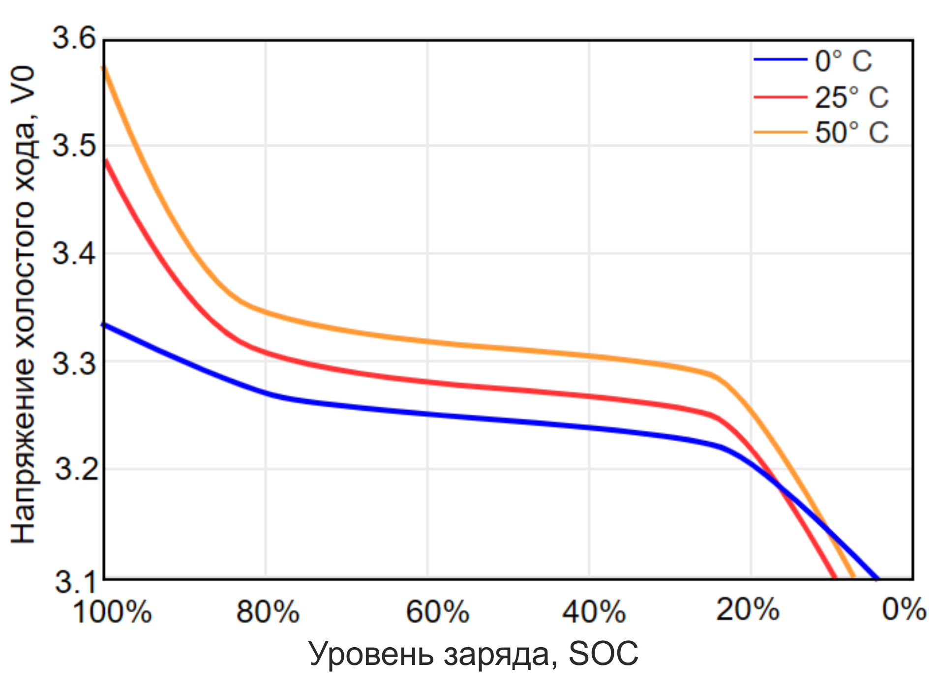
The graph shows examples of battery characteristics that vary depending on temperature and charge level, given in the technical data sheet.
Use this unit to parameterize batteries with complex open-circuit voltage characteristics obtained from technical data sheets or experimental results. For a simpler representation of the battery, you can use the block Battery.
Block Battery (Table-Based) It has a measuring port that can be opened by setting the appropriate parameters. Measuring port SOC outputs the charge level value. Use this port to change the dependence of the load on the charge level, without resorting to the difficulties associated with measuring it. To open the port SOC, enable the parameter Expose measurement port and for the parameter Measurement output type set the value SOC.
When selecting an option Measurement output type values Charge in Coulombs The current battery charge (in coulombs) is output to the output port.
To use the thermal port, check the box Enable thermal port. The heat port represents the heat capacity of the battery.
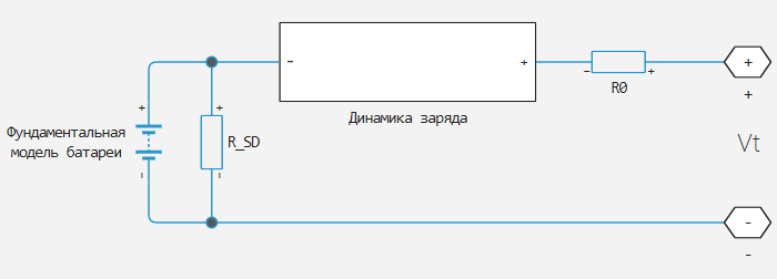
An equivalent battery circuit consists of a fundamental battery model, self-discharge resistance , models of charge dynamics and series resistance .
The fundamental battery model
This unit calculates the no-load voltage on a fundamental battery model by interpolating tabular data.:
where
-
— the voltage of the battery’s open circuit. Set the matrix of values using the parameter Open-circuit voltage, V0(SOC,T) if the parameter depends on temperature, or the vector Open-circuit voltage, V0(SOC) otherwise;
-
— this is the charge level, the ratio of the current charge to the rated battery capacity specified in the parameter Cell capacity, AH, taking into account the fading of the change in the capacity of the element specified in the parameter Percentage change in cell capacity, dAH(N, Tfade). Specify the reference values using the parameter Vector of state-of-charge values, SOC. The unit evaluates the rated capacity of the battery depending on the number of cycles and the temperature of the battery by interpolating the specified temperature-dependent decay characteristic and parameter Cell capacity, AH.
For the case when the extinction characteristic is obtained based on the data table:
For the case when the extinction characteristic is obtained on the basis of the equations:
The result of the expressions is measured in Cl. it is obtained from the following equation:
where
-
— the nominal capacity of the battery cell, the value is set in the parameter Cell capacity, AH, in Pendants;
-
— the reference number of discharge cycles for which a percentage change in battery parameters is set, the value is set in the parameter Number of discharge cycles, N;
-
— the current number of battery discharge cycles;
-
— percentage change in battery capacity after discharge cycles;
-
— battery temperature. Values are set in the parameter Vector of temperatures, T if the parameters depend on the temperature.
The block also simulates the serial resistance as a function of the charge level and temperature. Set the value matrix for the series resistance using the parameter Terminal resistance, R0(SOC,T) if the parameter depends on temperature, or the vector Terminal resistance, R0(SOC) otherwise.
Simulation of self-discharge
When the battery terminals are open, internal currents can still drain the battery. This behavior is called self-discharge. To enable this effect, check the box Self-discharge.
The unit simulates internal currents using resistance connected to the terminals of the fundamental battery model. You can specify tabular data for resistance using the parameter Self-discharge resistance, Rleak(T) if the parameter depends on the temperature, or Self-discharge resistance, Rleak otherwise.
Simulation of charge dynamics
Batteries are not able to respond instantly to load changes. It takes them some time to reach a stable state. This time-varying property is the result of battery charge dynamics and is modeled using sequential dynamic RC links in an equivalent circuit.
You can simulate the dynamics of battery charge using the parameter Charge dynamics:
-
No dynamics— the equivalent circuit does not contain dynamic links. There is no delay between the terminal voltage and the internal voltage of the fundamental battery. -
One time-constant dynamics— the equivalent circuit contains one RC link. Specify the time constant using the parameter First time constant, tau1(SOC,T) if the parameter depends on the temperature, or First time constant, tau1(SOC) otherwise. Also specify the resistance using the parameter First polarization resistance, R1(SOC,T) if the parameter depends on the temperature, or First polarization resistance, R1(SOC) otherwise. -
Two time-constant dynamics— the equivalent circuit contains two RC links. Specify the time constants using the parameters First time constant, tau1(SOC,T) and Second time constant, tau2(SOC,T) if the parameter depends on the temperature, or First time constant, tau1(SOC) and Second time constant, tau2(SOC) otherwise. Also specify the resistances using the parameters First polarization resistance, R1(SOC,T) and Second polarization resistance, R2(SOC,T) if the parameters depend on the temperature, or First polarization resistance, R1(SOC) and Second polarization resistance, R2(SOC) otherwise. -
Three time-constant dynamics— the equivalent circuit contains three RC links. Specify the time constants using the parameters First time constant, tau1(SOC,T), Second time constant, tau2(SOC,T) and Third time constant, tau3(SOC,T) if the parameter depends on the temperature, or First time constant, tau1(SOC), Second time constant, tau2(SOC), and Third time constant, tau3(SOC) otherwise. Also specify the resistances using the parameters First polarization resistance, R1(SOC,T), Second polarization resistance, R2(SOC,T) and Third polarization resistance, R3(SOC,T), if the parameters depend on temperature, or First polarization resistance, R1(SOC), Second polarization resistance, R2(SOC) and Third polarization resistance, R3(SOC) otherwise. -
Four time-constant dynamics— the equivalent circuit contains four RC links. Specify the time constants using the parameters First time constant, tau1(SOC,T), Second time constant, tau2(SOC,T), Third time constant, tau3(SOC,T) and Fourth time constant, tau4(SOC,T) if the parameter depends on the temperature, or First time constant, tau1(SOC), Second time constant, tau2(SOC), Third time constant, tau3(SOC) and Fourth time constant, tau4(SOC) otherwise. Also specify the resistances using the parameters First polarization resistance, R1(SOC,T), Second polarization resistance, R2(SOC,T), Third polarization resistance, R3(SOC,T) and Fourth polarization resistance, R4(SOC,T) if the parameters depend on the temperature, or First polarization resistance, R1(SOC), Second polarization resistance, R2(SOC), Third polarization resistance, R3(SOC) and Fourth polarization resistance, R4(SOC) otherwise. -
Five time-constant dynamics— the equivalent circuit contains five RC links. Specify the time constants using the parameters First time constant, tau1(SOC,T), Second time constant, tau2(SOC,T), Third time constant, tau3(SOC,T), Fourth time constant, tau4(SOC,T) and Fifth time constant, tau5(SOC,T) if the parameter depends on the temperature, or First time constant, tau1(SOC), Second time constant, tau2(SOC), Third time constant, tau3(SOC), Fourth time constant, tau4(SOC) and Fifth time constant, tau5(SOC) otherwise. Also specify the resistances using the parameters First polarization resistance, R1(SOC,T), Second polarization resistance, R2(SOC,T), Third polarization resistance, R3(SOC,T), Fourth polarization resistance, R4(SOC,T) and Fifth polarization resistance, R5(SOC,T) if the parameters depend on the temperature, or First polarization resistance, R1(SOC), Second polarization resistance, R2(SOC), Third polarization resistance, R3(SOC), Fourth polarization resistance, R4(SOC) and Fifth polarization resistance, R5(SOC) otherwise.
The figure shows an equivalent circuit for a block that has two time constants.

On the diagram:
-
and — resistance of dynamic links.
-
and — capacities of dynamic links. The time constant connects the values for each parallel circuit and using dependency .
-
— consistent resistance.
Simulation of battery fading
Battery fading is the deterioration of battery performance during repeated charge and discharge cycles. When the parameter Fade characteristic it matters Equations. battery decay is modeled by the formula as described below.
The open circuit voltage on the fundamental battery model decays in proportion to the number of discharge cycles :
where — percentage change in open circuit voltage after discharge cycles. Meaning is set by the parameter Change in open-circuit voltage after N discharge cycles (%).
|
Block Battery (Table-Based) tracks the current and integrates it over time. Number of discharge cycles increases by 1 each time a charge equal to the equivalent battery capacity is consumed. |
The nominal charge, on the basis of which the charge level is calculated, decays according to the following dependence on the number of discharge cycles:
All resistances in the battery model also decay according to a similar dependence on the number of discharge cycles.:
where
-
— -e resistance;
-
— percentage change of this resistance for cycles.
Depending on the unit settings, the resistances may include:
-
Sequential resistance — specify the percentage change for cycles using the parameter Change in terminal resistance after N discharge cycles (%).
-
Self—discharge resistance - specify the percentage change for cycles using the parameter Change in self-discharge resistance after N discharge cycles (%).
-
The first resistance of the charge dynamics — specify the percentage change for cycles using the parameter Change in first polarization resistance after N discharge cycles (%).
-
The second resistance of the charge dynamics — specify the percentage change for cycles using the parameter Change in second polarization resistance after N discharge cycles (%).
-
The third resistance of the charge dynamics — specify the percentage change for cycles using the parameter Change in third polarization resistance after N discharge cycles (%).
-
The fourth resistance of the charge dynamics — specify the percentage change for cycles using the parameter Change in fourth polarization resistance after N discharge cycles (%).
-
Fifth resistance of charge dynamics — specify the percentage change for cycles using the parameter Change in fifth polarization resistance after N discharge cycles (%).
|
You can also model the battery’s decay characteristics using tables of values that are independent or temperature-dependent. When you select either of these two options, the block parameters change accordingly. |
Modeling of thermal effects
The battery temperature is determined by summing up all ohmic losses included in the model:
where
-
— battery heat capacity;
-
Index respond -the source of ohmic losses. Depending on how the unit is configured, losses may include:
-
consistent resistance;
-
self-discharge resistance;
-
the first segment of charge dynamics;
-
the second segment of charge dynamics;
-
the third segment of charge dynamics;
-
the fourth segment of charge dynamics;
-
the fifth segment of charge dynamics.
-
-
— voltage drop on -oh resistance;
-
— - the resistance.
Simulation of battery aging
The unit allows you to simulate the deterioration of battery performance that occurs when the battery is not in use during storage. Aging affects both internal resistance and capacitance. In particular, the increase in resistance depends on various mechanisms, such as the formation of a solid Electrolyte Interface (SEI) at the anode and cathode and corrosion of the conductors. These processes mainly depend on the storage temperature, charge level, and time.
To simulate aging, you need to specify for the parameter Modeling option meaning:
-
Equation-based; -
Tabulated: temperature; -
Tabulated: time and temperature.
|
Block Battery (Table-Based) it takes into account aging only during initialization. When checking the boxes Internal resistance calendar aging or Capacity calendar aging, the block opens the parameter Vector of time intervals, which represents the battery’s aging time before starting the simulation. During the simulation, aging is not taken into account. |
Calculation based on the combination of equations
The increase in the resistance of the battery terminals as a result of aging is determined by the equation:
where
-
— parameter value Normalized open-circuit voltage during storage, V/Vnom;
-
— the value of the Internal resistance parameter;
-
— storage time values obtained from the parameter Vector of time intervals;
-
— the corresponding temperature values obtained from the parameter Vector of temperatures, T;
-
— parameter value Terminal resistance linear scaling for voltage, b;
-
— parameter value Terminal resistance constant offset for voltage, c;
-
— parameter value Terminal resistance temperature-dependent exponential increase, d;
-
— parameter value Terminal resistance time exponent, a;
-
— the elementary charge of an electron, in Cl;
-
— Boltzmann constant, in J/K.
This equation determines the decrease in battery capacity as a result of aging.:
where
-
— the value of the initial capacity parameter;
-
— parameter value Capacity linear scaling for voltage, b;
-
— parameter value Capacity constant offset for voltage, c;
-
— the value of the Capacity temperature-dependent exponential increase parameter, d;
-
— the value of the Capacity time constant parameter, a.
If for the parameter Storage condition There is a value Specify state-of-charge during storage, the unit converts the charge level during storage to a normalized open circuit voltage using a tabulated voltage depending on the charge level and temperature during storage.
Calculation according to tables: dependence only on temperature.
The resistance of aging pins is the product between the resistance of the pins. , a percentage increase in resistance , and an exponential (power law) describing the dependence of aging on time:
where
-
— parameter value Vector of storage temperatures;
-
and — these are the time values obtained from the parameter Vector of time intervals;
-
it is assumed to be zero;
-
— the point in time at which the increase in resistance is measured .
A similar equation is used to calculate the battery capacity in case of obsolescence.
Variables
Use the parameter group Initial Targets to set the priority and initial target values for the block parameter variables before modeling. For more information, see Configuring physical blocks using target values.
Ports
Conserving
#
+
—
positive contact
electricity
Details
The electrical port connected to the positive contact of the battery.
| Program usage name |
|
#
−
—
negative contact
electricity
Details
The electrical port connected to the negative contact of the battery.
| Program usage name |
|
#
H
—
battery thermal port
warm
Details
The heat capacity of the battery.
Dependencies
To use this port, check the box for the parameter Enable thermal port.
| Program usage name |
|
Output
#
q
—
current battery charge, Kl
scalar
Details
Internal charge in coulombs. Use this output port to change the behavior of the load depending on the charge, without resorting to the complexities of building a charge meter.
Dependencies
To use this port, check the box for the parameter Expose measurement port, and for the parameter Measurement output type set the value Charge in Coulombs.
| Data types |
|
| Complex numbers support |
No |
#
SOC
—
Battery charge level
scalar
Details
The charge level. Use this output port to change the load behavior depending on the charge level, without resorting to the complexities of building a charge meter.
Charge level is a normalized value equal to the ratio of the current charge to the rated capacity of the battery . The unit evaluates the current battery charge by integrating the output current of the battery terminals. To convert the state of charge to an actual charge, you must use the correct rated battery capacity for each temperature.
Dependencies
To use this port, check the box for the parameter Expose measurement port, and for the parameter Measurement output type set the value SOC.
| Data types |
|
| Complex numbers support |
No |
Parameters
Main
# Vector of state-of-charge values, SOC — vector of charge level values (SOC) for tabular data
Details
A vector of charge level values for tabular data. The elements of the vector must go in ascending order. Meaning — this is the ratio of the current battery charge to the rated capacity of the battery . It is necessary to ensure that for each temperature, when the charge is equal to the battery capacity specified in the parameter Cell capacity, AH assuming a fresh battery with the number of cycles and .
for and .
| Default value |
|
| Program usage name |
|
| Evaluatable |
Yes |
# Temperature dependent tables — select whether the battery settings depend on the temperature.
Details
Select whether the battery settings depend on the temperature.
| Default value |
|
| Program usage name |
|
| Evaluatable |
No |
# Current directionality — enables current direction accounting
Details
If this option is selected, the resistance of the terminals will depend on the current direction.
| Default value |
|
| Program usage name |
|
| Evaluatable |
No |
#
Vector of temperatures, T —
vector of temperature values for tabular data
K | degC | degF | degR | deltaK | deltadegC | deltadegF | deltadegR
Details
A vector of temperature values for calculating temperature-dependent parameters. The values of the vector must be positive and ascending.
Dependencies
To use this option, check the box Temperature dependent tables.
| Units |
|
| Default value |
|
| Program usage name |
|
| Evaluatable |
Yes |
#
Open-circuit voltage, V0(SOC,T) —
no-load voltage depending on charge level and temperature
V | uV | mV | kV | MV
Details
The matrix of open-circuit voltage values of the fundamental battery model at the specified SOC temperature values.
Dependencies
To use this option, check the box Temperature dependent tables.
| Units |
|
| Default value |
|
| Program usage name |
|
| Evaluatable |
Yes |
#
Open-circuit voltage, V0(SOC) —
No-load voltage
V | uV | mV | kV | MV
Details
The vector of open-circuit voltage values of the fundamental battery model at the specified SOC values.
Dependencies
To use this option, uncheck the box. Temperature dependent tables.
| Units |
|
| Default value |
|
| Program usage name |
|
| Evaluatable |
Yes |
#
Terminal voltage operating range [Min, Max] —
the operating voltage range at the terminals
V | uV | mV | kV | MV
Details
The operating voltage range at the terminals. This parameter should be a vector of two elements that defines the minimum and maximum voltage values at the terminals.
| Units |
|
| Default value |
|
| Program usage name |
|
| Evaluatable |
Yes |
#
Terminal resistance, R0(SOC,T) —
consistent battery resistance depending on charge level and temperature
Ohm | mOhm | kOhm | MOhm | GOhm
Details
A matrix of values for the serial resistance of the battery at the specified SOC and temperature values.
Dependencies
To use this option, check the box Temperature dependent tables.
| Units |
|
| Default value |
|
| Program usage name |
|
| Evaluatable |
Yes |
#
Terminal resistance, R0(SOC) —
consistent battery resistance
Ohm | mOhm | kOhm | MOhm | GOhm
Details
The vector of values of the serial resistance of the battery at the specified SOC values.
Dependencies
To use this option, uncheck the box. Temperature dependent tables.
| Units |
|
| Default value |
|
| Program usage name |
|
| Evaluatable |
Yes |
#
Terminal resistance during discharging, R0(SOC,T) —
consistent battery resistance during the discharge phase depending on the charge level and temperature
Ohm | mOhm | kOhm | MOhm | GOhm
Details
A matrix of values of the serial resistance of the battery during the discharge phase at the specified SOC and temperature values.
Dependencies
To use this option, check the box Temperature dependent tables and Current directionality.
| Units |
|
| Default value |
|
| Program usage name |
|
| Evaluatable |
Yes |
#
Terminal resistance during discharging, R0(SOC) —
consistent battery resistance during the discharge phase
Ohm | mOhm | kOhm | MOhm | GOhm
Details
The vector of values of the serial resistance of the battery during the discharge phase at the specified SOC values.
Dependencies
To use this option, uncheck the box. Temperature dependent tables and check the box Current directionality.
| Units |
|
| Default value |
|
| Program usage name |
|
| Evaluatable |
Yes |
#
Terminal resistance during charging, R0(SOC,T) —
consistent battery resistance during the charging phase
Ohm | mOhm | kOhm | MOhm | GOhm
Details
A matrix of values of the serial resistance of the battery during the charging phase at the specified SOC and temperature values.
Dependencies
To use this option, check the box Temperature dependent tables and Current directionality.
| Units |
|
| Default value |
|
| Program usage name |
|
| Evaluatable |
Yes |
#
Terminal resistance during charging, R0(SOC) —
consistent battery resistance during the charging phase
Ohm | mOhm | kOhm | MOhm | GOhm
Details
The vector of values of the serial resistance of the battery during the charging phase at the specified SOC values.
Dependencies
To use this option, uncheck the box. Temperature dependent tables and check the box Current directionality.
| Units |
|
| Default value |
|
| Program usage name |
|
| Evaluatable |
Yes |
#
Cell capacity, AH —
battery capacity at full charge
C | nC | uC | mC | nA*s | uA*s | mA*s | A*s | mA*hr | A*hr | kA*hr | MA*hr
Details
Battery capacity. The unit calculates the charge level by dividing the accumulated charge by this value. The unit calculates the accumulated charge by integrating the battery current.
| Units |
|
| Default value |
|
| Program usage name |
|
| Evaluatable |
Yes |
# Self-discharge — select whether you want to simulate the battery’s self-discharge resistance.
Details
Select whether you want to simulate the battery’s self-discharge resistance. The unit models this effect as a resistance connected in parallel to the fundamental battery model.
As the temperature increases, the self-discharge resistance decreases, which leads to an increase in self-discharge. If the resistance decrease occurs too quickly, thermal discharge of the battery and instability of the numerical solution may occur. You can eliminate this instability by making any of these changes.:
-
Reduce thermal resistance;
-
Reduce the gradient of self-discharge resistance depending on temperature;
-
Increase the self-discharge resistance.
| Default value |
|
| Program usage name |
|
| Evaluatable |
No |
#
Self-discharge resistance, Rleak(T) —
battery self-discharge resistance depending on temperature
Ohm | mOhm | kOhm | MOhm | GOhm
Details
Data for calculating the battery self-discharge resistance at the specified temperature values. This resistance is connected to the terminals of the fundamental battery model.
Dependencies
To use this option, check the box Temperature dependent tables and Self-discharge.
| Units |
|
| Default value |
|
| Program usage name |
|
| Evaluatable |
Yes |
#
Self-discharge resistance, Rleak —
battery self-discharge resistance
Ohm | mOhm | kOhm | MOhm | GOhm
Details
Data for calculating battery self-discharge resistance. This resistance is connected to the terminals of the fundamental battery model.
Dependencies
To use this option, uncheck the box. Temperature dependent tables and check the box Self-discharge.
| Units |
|
| Default value |
|
| Program usage name |
|
| Evaluatable |
Yes |
#
Extrapolation method for all tables —
extrapolation method for tables
Linear | Nearest
Details
Extrapolation method for all parameters calculated from tables:
-
Linear— evaluates values outside the data set by creating a tangent line at the end of the known data and extending it beyond this limit. -
Nearest— extrapolates the value at a point to the value at the nearest grid point.
| Values |
|
| Default value |
|
| Program usage name |
|
| Evaluatable |
No |
# Expose measurement port — display of the measuring port
Details
If the check box is selected Expose measurement port, then an additional (measuring) port appears in the block.
| Default value |
|
| Program usage name |
|
| Evaluatable |
No |
#
Measurement output type —
signal selection in the measuring port
Charge in Coulombs | SOC
Details
The parameter has two values:
-
SOC— charge level values are sent to the outputSOC. -
Charge in Coulombs— charge values are sent to the outputqin Pendants.
Dependencies
To use this option, check the box Expose measurement port.
| Values |
|
| Default value |
|
| Program usage name |
|
| Evaluatable |
No |
Dynamics
#
Charge dynamics —
battery charge dynamics model
No dynamics | One time-constant dynamics | Two time-constant dynamics | Three time-constant dynamics | Four time-constant dynamics | Five time-constant dynamics
Details
Choose a way to simulate the dynamics of battery charge. This parameter determines the number of RC links in the equivalent circuit.:
-
No dynamics— the equivalent circuit does not contain dynamic RC links. There is no delay between the terminal voltage and the internal voltage of the fundamental battery. -
One time-constant dynamics— the equivalent circuit contains one RC link. -
Two time-constant dynamics— the equivalent circuit contains two RC links. -
Three time-constant dynamics— the equivalent circuit contains three RC links. -
Four time-constant dynamics— the equivalent circuit contains four RC links. -
Five time-constant dynamics— the equivalent circuit contains five RC links.
| Values |
|
| Default value |
|
| Program usage name |
|
| Evaluatable |
No |
#
First polarization resistance, R1(SOC,T) —
resistance of the first dynamic link, depending on temperature
Ohm | mOhm | kOhm | MOhm | GOhm
Details
A matrix of resistance values for the first RC link at the specified SOC and temperature values. This parameter primarily affects the ohmic losses of the RC link.
Dependencies
To use this option, check the box Temperature dependent tables and set for the parameter Charge dynamics meaning One time-constant dynamics, Two time-constant dynamics, Three time-constant dynamics, Four time-constant dynamics or Five time-constant dynamics.
| Units |
|
| Default value |
|
| Program usage name |
|
| Evaluatable |
Yes |
#
First polarization resistance, R1(SOC) —
resistance of the first dynamic link
Ohm | mOhm | kOhm | MOhm | GOhm
Details
The vector of resistance values of the first RC link at the specified SOC values. This parameter primarily affects the ohmic losses of the RC link.
Dependencies
To use this option, check the box Temperature dependent tables and set for the parameter Charge dynamics meaning One time-constant dynamics, Two time-constant dynamics, Three time-constant dynamics, Four time-constant dynamics or Five time-constant dynamics.
| Units |
|
| Default value |
|
| Program usage name |
|
| Evaluatable |
Yes |
#
First time constant, tau1(SOC,T) —
the time constant of the first dynamic link, depending on temperature
s | ns | us | ms | min | hr | d
Details
A matrix of time constant values for the first RC link at the specified SOC and temperature values.
Dependencies
To use this option, check the box Temperature dependent tables and set for the parameter Charge dynamics meaning One time-constant dynamics, Two time-constant dynamics, Three time-constant dynamics, Four time-constant dynamics or Five time-constant dynamics.
| Units |
|
| Default value |
|
| Program usage name |
|
| Evaluatable |
Yes |
#
First time constant, tau1(SOC) —
the time constant of the first dynamic link
s | ns | us | ms | min | hr | d
Details
A vector of time constant values for the first RC link at the specified SOC values.
Dependencies
To use this option, check the box Temperature dependent tables and set for the parameter Charge dynamics meaning One time-constant dynamics, Two time-constant dynamics, Three time-constant dynamics, Four time-constant dynamics or Five time-constant dynamics.
| Units |
|
| Default value |
|
| Program usage name |
|
| Evaluatable |
Yes |
#
Second polarization resistance, R2(SOC,T) —
resistance of the second dynamic link, depending on temperature
Ohm | mOhm | kOhm | MOhm | GOhm
Details
A matrix of resistance values of the second RC link at the specified SOC and temperature values. This parameter primarily affects the ohmic losses of the RC link.
Dependencies
To use this option, check the box Temperature dependent tables and set for the parameter Charge dynamics meaning Two time-constant dynamics, Three time-constant dynamics, Four time-constant dynamics or Five time-constant dynamics.
| Units |
|
| Default value |
|
| Program usage name |
|
| Evaluatable |
Yes |
#
Second polarization resistance, R2(SOC) —
resistance of the second RC link
Ohm | mOhm | kOhm | MOhm | GOhm
Details
The vector of resistance values for the second RC link at the specified SOC values. This parameter primarily affects the ohmic losses of the RC link.
Dependencies
To use this option, check the box Temperature dependent tables and set for the parameter Charge dynamics meaning Two time-constant dynamics, Three time-constant dynamics, Four time-constant dynamics or Five time-constant dynamics.
| Units |
|
| Default value |
|
| Program usage name |
|
| Evaluatable |
Yes |
#
Second time constant, tau2(SOC,T) —
the time constant of the second dynamic link, depending on temperature
s | ns | us | ms | min | hr | d
Details
A matrix of time constant values for the second RC link at the specified SOC and temperature values.
Dependencies
To use this option, check the box Temperature dependent tables and set for the parameter Charge dynamics meaning Two time-constant dynamics, Three time-constant dynamics, Four time-constant dynamics or Five time-constant dynamics.
| Units |
|
| Default value |
|
| Program usage name |
|
| Evaluatable |
Yes |
#
Second time constant, tau2(SOC) —
the time constant of the second dynamic link
s | ns | us | ms | min | hr | d
Details
A vector of time constant values for the second RC link at the specified SOC values.
Dependencies
To use this option, check the box Temperature dependent tables and set for the parameter Charge dynamics meaning Two time-constant dynamics, Three time-constant dynamics, Four time-constant dynamics or Five time-constant dynamics.
| Units |
|
| Default value |
|
| Program usage name |
|
| Evaluatable |
Yes |
#
Third polarization resistance, R3(SOC,T) —
resistance of the third dynamic link, depending on temperature
Ohm | mOhm | kOhm | MOhm | GOhm
Details
A matrix of resistance values for the third RC link at the specified SOC and temperature values. This parameter primarily affects the ohmic losses of the RC link.
Dependencies
To use this option, check the box Temperature dependent tables and set for the parameter Charge dynamics meaning Three time-constant dynamics, Four time-constant dynamics or Five time-constant dynamics.
| Units |
|
| Default value |
|
| Program usage name |
|
| Evaluatable |
Yes |
#
Third polarization resistance, R3(SOC) —
resistance of the third dynamic link
Ohm | mOhm | kOhm | MOhm | GOhm
Details
The vector of resistance values of the third RC link at the specified SOC values. This parameter primarily affects the ohmic losses of the RC link.
Dependencies
To use this option, check the box Temperature dependent tables and set for the parameter Charge dynamics meaning Three time-constant dynamics, Four time-constant dynamics or Five time-constant dynamics.
| Units |
|
| Default value |
|
| Program usage name |
|
| Evaluatable |
Yes |
#
Third time constant, tau3(SOC,T) —
the time constant of the third dynamic link, depending on temperature
s | ns | us | ms | min | hr | d
Details
A matrix of time constant values for the third RC link at the specified SOC and temperature values.
Dependencies
To use this option, check the box Temperature dependent tables and set for the parameter Charge dynamics meaning Three time-constant dynamics, Four time-constant dynamics or Five time-constant dynamics.
| Units |
|
| Default value |
|
| Program usage name |
|
| Evaluatable |
Yes |
#
Third time constant, tau3(SOC) —
the time constant of the third dynamic link
s | ns | us | ms | min | hr | d
Details
A vector of time constant values for the third RC link at the specified SOC values.
Dependencies
To use this option, check the box Temperature dependent tables and set for the parameter Charge dynamics meaning Three time-constant dynamics, Four time-constant dynamics or Five time-constant dynamics.
| Units |
|
| Default value |
|
| Program usage name |
|
| Evaluatable |
Yes |
#
Fourth polarization resistance, R4(SOC,T) —
resistance of the fourth dynamic link, depending on temperature
Ohm | mOhm | kOhm | MOhm | GOhm
Details
A matrix of resistance values for the fourth RC link at the specified SOC and temperature values. This parameter primarily affects the ohmic losses of the RC link.
Dependencies
To use this option, check the box Temperature dependent tables and set for the parameter Charge dynamics meaning Four time-constant dynamics or Five time-constant dynamics.
| Units |
|
| Default value |
|
| Program usage name |
|
| Evaluatable |
Yes |
#
Fourth polarization resistance, R4(SOC) —
resistance of the fourth dynamic link
Ohm | mOhm | kOhm | MOhm | GOhm
Details
The vector of resistance values of the fourth RC link at the specified SOC values. This parameter primarily affects the ohmic losses of the RC link.
Dependencies
To use this option, check the box Temperature dependent tables and set for the parameter Charge dynamics meaning Four time-constant dynamics or Five time-constant dynamics.
| Units |
|
| Default value |
|
| Program usage name |
|
| Evaluatable |
Yes |
#
Fourth time constant, tau4(SOC,T) —
the time constant of the fourth dynamic link, depending on temperature
s | ns | us | ms | min | hr | d
Details
A matrix of time constant values for the fourth RC link at the specified SOC values.
Dependencies
To use this option, check the box Temperature dependent tables and set for the parameter Charge dynamics meaning Four time-constant dynamics or Five time-constant dynamics.
| Units |
|
| Default value |
|
| Program usage name |
|
| Evaluatable |
Yes |
#
Fourth time constant, tau4(SOC) —
the time constant of the fourth dynamic link
s | ns | us | ms | min | hr | d
Details
A vector of time constant values for the fourth RC link at the specified SOC values.
Dependencies
To use this option, check the box Temperature dependent tables and set for the parameter Charge dynamics meaning Four time-constant dynamics or Five time-constant dynamics.
| Units |
|
| Default value |
|
| Program usage name |
|
| Evaluatable |
Yes |
#
Fifth polarization resistance, R5(SOC,T) —
resistance of the fifth dynamic link, depending on temperature
Ohm | mOhm | kOhm | MOhm | GOhm
Details
A matrix of resistance values for the fifth RC link at the specified SOC and temperature values. This parameter primarily affects the ohmic losses of the RC link.
Dependencies
To use this option, check the box Temperature dependent tables and set for the parameter Charge dynamics meaning Five time-constant dynamics.
| Units |
|
| Default value |
|
| Program usage name |
|
| Evaluatable |
Yes |
#
Fifth polarization resistance, R5(SOC) —
resistance of the fifth dynamic link
Ohm | mOhm | kOhm | MOhm | GOhm
Details
The matrix of resistance values of the fifth RC link at the specified SOC values. This parameter primarily affects the ohmic losses of the RC link.
Dependencies
To use this option, check the box Temperature dependent tables and set for the parameter Charge dynamics meaning Five time-constant dynamics.
| Units |
|
| Default value |
|
| Program usage name |
|
| Evaluatable |
Yes |
#
Fifth time constant, tau5(SOC,T) —
the time constant of the fifth dynamic link, depending on temperature
s | ns | us | ms | min | hr | d
Details
A matrix of time constant values for the fifth RC link at the specified SOC and temperature values.
Dependencies
To use this option, check the box Temperature dependent tables and set for the parameter Charge dynamics meaning Five time-constant dynamics.
| Units |
|
| Default value |
|
| Program usage name |
|
| Evaluatable |
Yes |
#
Fifth time constant, tau5(SOC) —
the time constant of the fifth dynamic link
s | ns | us | ms | min | hr | d
Details
A matrix of time constant values for the fifth RC link at the specified SOC values.
Dependencies
To use this option, check the box Temperature dependent tables and set for the parameter Charge dynamics meaning Five time-constant dynamics.
| Units |
|
| Default value |
|
| Program usage name |
|
| Evaluatable |
Yes |
Fade
# Enable fade — enabling battery drain simulation
Details
If a USB flash drive is installed Enable fade, then in the block it becomes possible to set parameters for simulating battery fading.
| Default value |
|
| Program usage name |
|
| Evaluatable |
No |
#
Fade characteristic —
the method of modeling extinction
Equations | Lookup tables (temperature independent) | Lookup tables (temperature dependent)
Details
Choose a method for modeling the extinction characteristic:
-
Equations— calculation of parameters using formulas. The capacity of the cell and the resistance of the terminals will be proportional while the open circuit voltage will be proportional to . If self-discharge resistance or any number of dynamic sections are enabled, their values will be proportional. . -
Lookup tables (temperature independent)— set tabular data for percentage parameter changes depending on . -
Lookup tables (temperature dependent)— set tabular data for percentage parameter changes depending on and temperature.
Dependencies
To use this option, check the box Enable fade.
| Values |
|
| Default value |
|
| Program usage name |
|
| Evaluatable |
No |
# Number of discharge cycles, N — the reference number of cycles for calculating the percentage change
Details
The number of charge-discharge cycles during which the indicated percentage changes occur.
Dependencies
To use this option, check the box Enable fade and for the parameter Fade characteristic set the value Equations.
| Default value |
|
| Program usage name |
|
| Evaluatable |
Yes |
# Change in open-circuit voltage after N discharge cycles (%) — percentage change in open circuit voltage after N discharge cycles
Details
Percentage change in open circuit voltage after the battery has passed discharge cycles.
Dependencies
To use this option, check the box Enable fade and for the parameter Fade characteristic set the value Equations.
| Default value |
|
| Program usage name |
|
| Evaluatable |
Yes |
# Change in terminal resistance after N discharge cycles (%) — percentage change in series resistance after N discharge cycles
Details
Percentage change in serial resistance after the battery has passed discharge cycles.
Dependencies
To use this option, check the box Enable fade and for the parameter Fade characteristic set the value Equations.
| Default value |
|
| Program usage name |
|
| Evaluatable |
Yes |
# Change in cell capacity after N discharge cycles (%) — percentage change in cell capacity after N discharge cycles
Details
Percentage change in cell capacity after the battery has passed discharge cycles.
Dependencies
To use this option, check the box Enable fade and for the parameter Fade characteristic set the value Equations.
| Default value |
|
| Program usage name |
|
| Evaluatable |
Yes |
# Change in self-discharge resistance after N discharge cycles (%) — percentage change in self-discharge resistance after N discharge cycles
Details
Percentage change in self-discharge resistance after the battery has passed discharge cycles.
Dependencies
To use this option, check the box Enable fade and for the parameter Fade characteristic set the value Equations.
| Default value |
|
| Program usage name |
|
| Evaluatable |
Yes |
# Change in first polarization resistance after N discharge cycles (%) — percentage change of the first RC resistance after N discharge cycles
Details
Percentage change in resistance of the first RC link after the battery has passed discharge cycles.
Dependencies
To use this option, check the box Enable fade, set for the parameter Fade characteristic meaning Equations and set for the parameter Charge dynamics meaning One time-constant dynamics, Two time-constant dynamics, Three time-constant dynamics, Four time-constant dynamics or Five time-constant dynamics.
| Default value |
|
| Program usage name |
|
| Evaluatable |
Yes |
# Change in second polarization resistance after N discharge cycles (%) — percentage change of the second RC resistance after N discharge cycles
Details
Percentage change in resistance of the second RC link after the battery has passed discharge cycles.
Dependencies
To use this option, check the box Enable fade, set for the parameter Fade characteristic meaning Equations and set for the parameter Charge dynamics meaning Two time-constant dynamics, Three time-constant dynamics, Four time-constant dynamics or Five time-constant dynamics.
| Default value |
|
| Program usage name |
|
| Evaluatable |
Yes |
# Change in third polarization resistance after N discharge cycles (%) — percentage change of the third RC resistance after N discharge cycles
Details
Percentage change in resistance of the third RC link after the battery has passed discharge cycles.
Dependencies
To use this option, check the box Enable fade, set for the parameter Fade characteristic meaning Equations and set for the parameter Charge dynamics meaning Three time-constant dynamics, Four time-constant dynamics or Five time-constant dynamics.
| Default value |
|
| Program usage name |
|
| Evaluatable |
Yes |
# Change in fourth polarization resistance after N discharge cycles (%) — percentage change of the fourth RC resistance after N discharge cycles
Details
Percentage change in resistance of the fourth RC link after the battery has passed discharge cycles.
Dependencies
To use this option, check the box Enable fade, set for the parameter Fade characteristic meaning Equations and set for the parameter Charge dynamics meaning Four time-constant dynamics or Five time-constant dynamics.
| Default value |
|
| Program usage name |
|
| Evaluatable |
Yes |
# Change in fifth polarization resistance after N discharge cycles (%) — percentage change of the fifth RC resistance after N discharge cycles
Details
Percentage change in resistance of the fifth RC link after the battery has passed discharge cycles.
Dependencies
To use this option, check the box Enable fade, set for the parameter Fade characteristic meaning Equations and set for the parameter Charge dynamics meaning Five time-constant dynamics.
| Default value |
|
| Program usage name |
|
| Evaluatable |
Yes |
# Vector of discharge cycle values, N — the vector of the number of cycles for the percentage change in parameters
Details
The vector of values of charge-discharge cycles, during which the specified percentage changes in parameters occur.
Dependencies
To use this option, check the box Enable fade and set for the parameter Fade characteristic meaning Lookup tables (temperature independent) or Lookup tables (temperature dependent).
| Default value |
|
| Program usage name |
|
| Evaluatable |
Yes |
#
Vector of temperatures for fade data, Tfade —
the vector of temperatures for which the tables of calculation of extinction are compiled
K | degC | degF | degR | deltaK | deltadegC | deltadegF | deltadegR
Details
The vector of temperatures for which the tables of calculation of extinction with dependence on temperatures are compiled. These temperatures are completely independent of the parameter Vector of temperatures, T.
Dependencies
To use this option, check the box Enable fade and set for the parameter Fade characteristic meaning Lookup tables (temperature dependent).
| Units |
|
| Default value |
|
| Program usage name |
|
| Evaluatable |
Yes |
# Percentage change in open-circuit voltage, dV0(N) — percentage change in the no-load voltage after N discharge cycles
Details
The vector of the percentage change in the open circuit voltage after the battery has passed discharge cycles.
Dependencies
To use this option, check the box Enable fade and set for the parameter Fade characteristic meaning Lookup tables (temperature independent).
| Default value |
|
| Program usage name |
|
| Evaluatable |
Yes |
# Percentage change in terminal resistance, dR0(N) — percentage change in series resistance after N discharge cycles
Details
The vector of the percentage change in serial resistance after the battery has passed discharge cycles.
Dependencies
To use this option, check the box Enable fade and set for the parameter Fade characteristic meaning Lookup tables (temperature independent).
| Default value |
|
| Program usage name |
|
| Evaluatable |
Yes |
# Percentage change in cell capacity, dAH(N) — percentage change in cell capacity after N discharge cycles
Details
The vector of the percentage change in cell capacity after the battery has passed discharge cycles.
Dependencies
To use this option, check the box Enable fade and set for the parameter Fade characteristic meaning Lookup tables (temperature independent).
| Default value |
|
| Program usage name |
|
| Evaluatable |
Yes |
# Percentage change in self-discharge resistance, dRleak(N) — percentage change in self-discharge resistance after N discharge cycles
Details
The vector of the percentage change in self-discharge resistance after the battery has passed discharge cycles.
Dependencies
To use this option, check the box Enable fade and Self-discharge and set for the parameter Fade characteristic meaning Lookup tables (temperature independent).
| Default value |
|
| Program usage name |
|
| Evaluatable |
Yes |
# Percentage change in first polarization resistance, dR1(N) — percentage change in resistance of the first RC link after N discharge cycles
Details
The vector of the percentage change in the resistance of the first RC link after the battery has passed discharge cycles.
Dependencies
To use this option, check the box Enable fade, set for the parameter Fade characteristic meaning Lookup tables (temperature independent) and set for the parameter Charge dynamics meaning One time-constant dynamics, Two time-constant dynamics, Three time-constant dynamics, Four time-constant dynamics or Five time-constant dynamics.
| Default value |
|
| Program usage name |
|
| Evaluatable |
Yes |
# Percentage change in second polarization resistance, dR2(N) — percentage change in resistance of the second RC link after N discharge cycles
Details
The vector of the percentage change in the resistance of the second RC link after the battery has passed discharge cycles.
Dependencies
To use this option, check the box Enable fade, set for the parameter Fade characteristic meaning Lookup tables (temperature independent) and set for the parameter Charge dynamics it matters Two time-constant dynamics, Three time-constant dynamics, Four time-constant dynamics or Five time-constant dynamics.
| Default value |
|
| Program usage name |
|
| Evaluatable |
Yes |
# Percentage change in third polarization resistance, dR3(N) — percentage change in resistance of the third RC link after N discharge cycles
Details
The vector of the percentage change in the resistance of the third RC link after the battery has passed discharge cycles.
Dependencies
To use this option, check the box Enable fade, set for the parameter Fade characteristic meaning Lookup tables (temperature independent) and set for the parameter Charge dynamics it matters Three time-constant dynamics, Four time-constant dynamics or Five time-constant dynamics.
| Default value |
|
| Program usage name |
|
| Evaluatable |
Yes |
# Percentage change in fourth polarization resistance, dR4(N) — percentage change in resistance of the fourth RC link after N discharge cycles
Details
The vector of the percentage change in the resistance of the fourth RC link after the battery has passed discharge cycles.
Dependencies
To use this option, check the box Enable fade, set for the parameter Fade characteristic meaning Lookup tables (temperature independent) and set for the parameter Charge dynamics it matters Four time-constant dynamics or Five time-constant dynamics.
| Default value |
|
| Program usage name |
|
| Evaluatable |
Yes |
# Percentage change in fifth polarization resistance, dR5(N) — percentage change in resistance of the fifth RC link after N discharge cycles
Details
The vector of the percentage change in the resistance of the fifth RC link after the battery has passed discharge cycles.
Dependencies
To use this option, check the box Enable fade, set for the parameter Fade characteristic meaning Lookup tables (temperature independent) and set for the parameter Charge dynamics it matters Five time-constant dynamics.
| Default value |
|
| Program usage name |
|
| Evaluatable |
Yes |
# Percentage change in open-circuit voltage, dV0(N,Tfade) — percentage change in no-load voltage after N discharge cycles and at Tfade temperatures
Details
Matrix of the percentage change in the open circuit voltage after the battery has passed discharge cycles and temperature dependent .
Dependencies
To use this option, check the box Enable fade and set for the parameter Fade characteristic meaning Lookup tables (temperature dependent).
| Default value |
|
| Program usage name |
|
| Evaluatable |
Yes |
# Percentage change in terminal resistance, dR0(N,Tfade) — percentage change in series resistance after N discharge cycles and at Tfade temperatures
Details
Matrix of the percentage change in serial resistance after the battery has passed discharge cycles and temperature dependent .
Dependencies
To use this option, check the box Enable fade and set for the parameter Fade characteristic meaning Lookup tables (temperature dependent).
| Default value |
|
| Program usage name |
|
| Evaluatable |
Yes |
# Percentage change in cell capacity, dAH(N,Tfade) — percentage change in cell capacity after N discharge cycles and at Tfade temperatures
Details
Matrix of the percentage change in cell capacity after the battery has passed discharge cycles and temperature dependent .
Dependencies
To use this option, check the box Enable fade and set for the parameter Fade characteristic meaning Lookup tables (temperature dependent).
| Default value |
|
| Program usage name |
|
| Evaluatable |
Yes |
# Percentage change in self-discharge resistance, dRleak(N,Tfade) — percentage change in self-discharge resistance after N discharge cycles and at Tfade temperatures
Details
Matrix of the percentage change in self-discharge resistance after the battery has passed discharge cycles and temperature dependent .
Dependencies
To use this option, check the box Enable fade and Self-discharge and set for the parameter Fade characteristic meaning Lookup tables (temperature dependent).
| Default value |
|
| Program usage name |
|
| Evaluatable |
Yes |
# Percentage change in first polarization resistance, dR1(N,Tfade) — percentage change in resistance of the first RC link after N discharge cycles and at Tfade temperatures
Details
The matrix of the percentage change in the resistance of the first RC link after the battery has passed discharge cycles and temperature dependent .
Dependencies
To use this option, check the box Enable fade, set for the parameter Fade characteristic meaning Lookup tables (temperature dependent) and set for the parameter Charge dynamics meaning One time-constant dynamics, Two time-constant dynamics, Three time-constant dynamics, Four time-constant dynamics or Five time-constant dynamics.
| Default value |
|
| Program usage name |
|
| Evaluatable |
Yes |
# Percentage change in second polarization resistance, dR2(N,Tfade) — percentage change in resistance of the second RC link after N discharge cycles and at Tfade temperatures
Details
The matrix of the percentage change in the resistance of the second RC link after the battery has passed discharge cycles and temperature dependent .
Dependencies
To use this option, check the box Enable fade, set for the parameter Fade characteristic meaning Lookup tables (temperature dependent) and set for the parameter Charge dynamics meaning Two time-constant dynamics, Three time-constant dynamics, Four time-constant dynamics or Five time-constant dynamics.
| Default value |
|
| Program usage name |
|
| Evaluatable |
Yes |
# Percentage change in third polarization resistance, dR3(N,Tfade) — percentage change in resistance of the third RC link after N discharge cycles and at Tfade temperatures
Details
The matrix of the percentage change in the resistance of the third RC link after the battery has passed discharge cycles and temperature dependent .
Dependencies
To use this option, check the box Enable fade, set for the parameter Fade characteristic meaning Lookup tables (temperature dependent) and set for the parameter Charge dynamics meaning Three time-constant dynamics, Four time-constant dynamics or Five time-constant dynamics.
| Default value |
|
| Program usage name |
|
| Evaluatable |
Yes |
# Percentage change in fourth polarization resistance, dR4(N,Tfade) — matrix of the percentage change in the resistance of the fourth RC link after N discharge cycles and at Tfade temperatures
Details
The matrix of the percentage change in the resistance of the fourth RC link after the battery has passed discharge cycles and temperature dependent .
Dependencies
To use this option, check the box Enable fade, set for the parameter Fade characteristic meaning Lookup tables (temperature dependent) and set for the parameter Charge dynamics meaning Four time-constant dynamics or Five time-constant dynamics.
| Default value |
|
| Program usage name |
|
| Evaluatable |
Yes |
# Percentage change in fifth polarization resistance, dR5(N,Tfade) — percentage change in resistance of the fifth RC link after N discharge cycles and at temperatures
Details
The matrix of the percentage change in the resistance of the fifth RC link after the battery has passed discharge cycles and temperature dependent .
Dependencies
To use this option, check the box Enable fade, set for the parameter Fade characteristic meaning Lookup tables (temperature dependent) and set for the parameter Charge dynamics meaning Five time-constant dynamics.
| Default value |
|
| Program usage name |
|
| Evaluatable |
Yes |
Calendar Aging
#
Modeling option —
a method for modeling aging
Equation-based | Tabulated: temperature | Tabulated: time and temperature
Details
A method for modeling the aging of internal resistance and capacitance:
-
Equation-based— calculation of parameters according to the equations; -
Tabulated: temperature— calculation based on tables of parameters that depend only on temperature; -
Tabulated: time and temperature— calculation based on tables of parameters that depend on both time and temperature.
Dependencies
To use this option, check the box Internal resistance calendar aging or check the box Capacity calendar aging.
| Values |
|
| Default value |
|
| Program usage name |
|
| Evaluatable |
No |
#
Vector of time intervals —
vector of time intervals
s | ns | us | ms | min | hr | d
Details
Vector of storage time intervals. The size of the vector must be equal in size to the vector from the parameter Vector of storage temperatures.
Dependencies
To use this option, check the box Internal resistance calendar aging or check the box Capacity calendar aging.
| Units |
|
| Default value |
|
| Program usage name |
|
| Evaluatable |
Yes |
#
Vector of storage temperatures —
vector of storage temperatures
K | degC | degF | degR | deltaK | deltadegC | deltadegF | deltadegR
Details
Vector of storage temperatures. The size of the vector must be equal in size to the vector from the parameter Vector of time intervals.
Dependencies
To use this option, check the box Internal resistance calendar aging or check the box Capacity calendar aging.
| Units |
|
| Default value |
|
| Program usage name |
|
| Evaluatable |
Yes |
#
Storage condition —
Storage conditions
Specify open-circuit voltage during storage | Specify state-of-charge during storage
Details
Battery storage conditions:
-
Specify open-circuit voltage during storage— the voltage of the open circuit during storage is indicated. -
Specify state-of-charge during storage— The charge level is indicated during storage.
Dependencies
To use this parameter, set for the parameter Modeling option meaning Equation-based.
| Values |
|
| Default value |
|
| Program usage name |
|
| Evaluatable |
No |
# Normalized open-circuit voltage during storage, V/Vnom — normalized open circuit voltage during storage
Details
Rated open circuit voltage during storage.
Dependencies
To use this parameter, set for the parameter Modeling option meaning Equation-based and set for the parameter Storage condition meaning Specify open-circuit voltage during storage.
| Default value |
|
| Program usage name |
|
| Evaluatable |
Yes |
# State of charge during storage — Charge level during storage
Details
The charge level during storage.
Dependencies
To use this parameter, set for the parameter Modeling option meaning Equation-based and set for the parameter Storage condition meaning Specify state-of-charge during storage.
| Default value |
|
| Program usage name |
|
| Evaluatable |
Yes |
# Internal resistance calendar aging — aging for internal resistance
Details
Whether to include the aging of the internal resistance of the battery.
| Default value |
|
| Program usage name |
|
| Evaluatable |
No |
# Terminal resistance linear scaling for voltage, b — linear voltage coefficient
Details
The linear voltage scaling factor for calculating terminal resistance.
Dependencies
To use this option, check the box Internal resistance calendar aging and set for the parameter Modeling option meaning Equation-based.
| Default value |
|
| Program usage name |
|
| Evaluatable |
Yes |
# Terminal resistance constant offset for voltage, c — constant offset for voltage to calculate terminal resistance
Details
A constant offset for the voltage to calculate the resistance of the terminals.
Dependencies
To use this option, check the box Internal resistance calendar aging and set for the parameter Modeling option meaning Equation-based.
| Default value |
|
| Program usage name |
|
| Evaluatable |
Yes |
#
Terminal resistance temperature-dependent exponential increase, d —
exponential coefficient for calculating terminal resistance
V | uV | mV | kV | MV
Details
An exponential coefficient for calculating terminal resistance depending on temperature.
Dependencies
To use this option, check the box Internal resistance calendar aging and set for the parameter Modeling option meaning Equation-based.
| Units |
|
| Default value |
|
| Program usage name |
|
| Evaluatable |
Yes |
# Terminal resistance time exponent, a — exponential coefficient for calculating resistance
Details
An exponential coefficient for calculating resistance depending on storage time.
Dependencies
To use this option, check the box Internal resistance calendar aging and set for the parameter Modeling option meaning Equation-based or Tabulated: temperature.
| Default value |
|
| Program usage name |
|
| Evaluatable |
Yes |
#
Vector of sampled temperatures for terminal resistance calendar aging, T_ar —
temperature vector for calculating the aging resistance of the terminals
K | degC | degF | degR | deltaK | deltadegC | deltadegF | deltadegR
Details
The temperature vector for calculating the aging of terminal resistances.
Dependencies
To use this option, check the box Internal resistance calendar aging and set for the parameter Modeling option meaning Tabulated: time and temperature or Tabulated: temperature.
| Units |
|
| Default value |
|
| Program usage name |
|
| Evaluatable |
Yes |
#
Vector of sampled storage time intervals for terminal resistance calendar aging, t_ar —
storage time intervals for calculating pin resistance aging
s | ns | us | ms | min | hr | d
Details
A vector of storage time intervals for calculating the aging resistance of pins.
Dependencies
To use this option, check the box Internal resistance calendar aging and set for the parameter Modeling option meaning Tabulated: time and temperature.
| Units |
|
| Default value |
|
| Program usage name |
|
| Evaluatable |
Yes |
# Percentage change in terminal resistance due to calendar aging, dR0(T_ar) — percentage change in terminal resistance as a result of aging
Details
The percentage change in terminal resistance as a result of aging. The length of the vector must be equal to the length of the vector .
Dependencies
To use this option, check the box Internal resistance calendar aging and set for the parameter Modeling option meaning Tabulated: temperature.
| Default value |
|
| Program usage name |
|
| Evaluatable |
Yes |
#
Time between terminal resistance beginning of life and dR(T_ar) measurement —
the time between the start of the service life and the measurement of dR(T_ar)
s | ns | us | ms | min | hr | d
Details
The time between the start of the service life and the measurement of dR(T_ar) to calculate the resistance of the terminals.
Dependencies
To use this option, check the box Internal resistance calendar aging and set for the parameter Modeling option meaning Tabulated: temperature.
| Units |
|
| Default value |
|
| Program usage name |
|
| Evaluatable |
Yes |
# Percentage change in terminal resistance due to calendar aging, dR0(t_ar,T_ar) — percentage change in terminal resistance due to aging
Details
A matrix of percentage changes in terminal resistance as a result of aging.
Dependencies
To use this option, check the box Internal resistance calendar aging and set for the parameter Modeling option meaning Tabulated: time and temperature.
| Default value |
|
| Program usage name |
|
| Evaluatable |
Yes |
# Capacity calendar aging — aging for capacity
Details
Whether to enable battery capacity aging.
| Default value |
|
| Program usage name |
|
| Evaluatable |
No |
# Capacity linear scaling for voltage, b — linear voltage coefficient
Details
Linear voltage coefficient for calculating capacity.
Dependencies
To use this option, check the box Capacity calendar aging and set for the parameter Modeling option meaning Equation-based.
| Default value |
|
| Program usage name |
|
| Evaluatable |
Yes |
# Capacity constant offset for voltage, c — constant offset for voltage to calculate capacitance
Details
A constant offset for the voltage to calculate the capacitance.
Dependencies
To use this option, check the box Capacity calendar aging and set for the parameter Modeling option meaning Equation-based.
| Default value |
|
| Program usage name |
|
| Evaluatable |
Yes |
#
Capacity temperature-dependent exponential decrease, d —
exponential coefficient for calculating capacity
V | uV | mV | kV | MV
Details
An exponential coefficient for calculating capacity.
Dependencies
To use this option, check the box Capacity calendar aging and set for the parameter Modeling option meaning Equation-based.
| Units |
|
| Default value |
|
| Program usage name |
|
| Evaluatable |
Yes |
# Capacity time exponent, a — exponential coefficient for calculating capacity depending on storage time
Details
An exponential coefficient for calculating the capacity depending on the storage time.
Dependencies
To use this option, check the box Internal resistance calendar aging and set for the parameter Modeling option meaning Equation-based or Tabulated: temperature.
| Default value |
|
| Program usage name |
|
| Evaluatable |
Yes |
#
Vector of sampled temperatures for capacity calendar aging, T_ac —
temperature vector for calculating capacity aging
K | degC | degF | degR | deltaK | deltadegC | deltadegF | deltadegR
Details
Temperature vector for calculating capacity aging.
Dependencies
To use this option, check the box Internal resistance calendar aging and set for the parameter Modeling option meaning Tabulated: time and temperature or Tabulated: temperature.
| Units |
|
| Default value |
|
| Program usage name |
|
| Evaluatable |
Yes |
#
Vector of sampled storage time intervals for capacity calendar aging, t_ac —
storage time intervals for calculating capacity aging
s | ns | us | ms | min | hr | d
Details
A vector of storage time intervals for calculating capacity aging.
Dependencies
To use this option, check the box Internal resistance calendar aging and set for the parameter Modeling option meaning Tabulated: time and temperature.
| Units |
|
| Default value |
|
| Program usage name |
|
| Evaluatable |
Yes |
# Percentage change in capacity due to calendar aging, dAH(T_ac) — percentage change in capacity as a result of aging
Details
The vector of values of the percentage change in capacity as a result of aging. The length of the vector must be equal to the length of the vector .
Dependencies
To use this option, check the box Capacity calendar aging and set for the parameter Modeling option meaning Tabulated: temperature.
| Default value |
|
| Program usage name |
|
| Evaluatable |
Yes |
#
Time between capacity beginning of life and dAH(T_ac) measurement —
the time between the start of the service life and the dAH measurement(T_ac)
s | ns | us | ms | min | hr | d
Details
The time between the start of the service life and measurement .
Dependencies
To use this option, check the box Capacity calendar aging and set for the parameter Modeling option meaning Tabulated: temperature.
| Units |
|
| Default value |
|
| Program usage name |
|
| Evaluatable |
Yes |
# Percentage change in capacity due to calendar aging, dAH(t_ac,T_ac) — percentage change in capacity due to aging depending on storage time and temperature
Details
A matrix of percentage changes in capacity as a result of aging, depending on the storage time and temperature.
Dependencies
To use this option, check the box Internal resistance calendar aging and set for the parameter Modeling option meaning Tabulated: time and temperature.
| Default value |
|
| Program usage name |
|
| Evaluatable |
Yes |
Thermal
# Enable thermal port — turning on the heat port
Details
Turn it on to use the thermal port.
| Default value |
|
| Program usage name |
|
| Evaluatable |
No |
#
Simulation temperature —
battery temperature
K | degC | degF | degR | deltaK | deltadegC | deltadegF | deltadegR
Details
The battery temperature used in the tables during the simulation when the thermal port is not activated.
Dependencies
To use this option, check the box Enable thermal port.
| Units |
|
| Default value |
|
| Program usage name |
|
| Evaluatable |
Yes |
#
Thermal mass —
the heat capacity associated with the thermal port
J/K | kJ/K
Details
The heat capacity associated with the thermal port H. It represents the energy needed to raise the temperature of the battery by one degree Kelvin.
Dependencies
To use this option, check the box Enable thermal port.
| Units |
|
| Default value |
|
| Program usage name |
|
| Evaluatable |
Yes |