Battery
The battery model.
blockType: AcausalElectricPowerSystems.Sources.Battery
|
Path in the library: |

Description
Block Battery It is a simple battery model. You can also use the charge output port and the thermal port of the battery.
To measure the internal battery charge level, in the section Main check the box for the parameter Expose charge measurement port. This action displays the additional q port, which outputs the current battery charge value. Use this functionality to change the behavior of the load depending on the state of charge, without resorting to the complexities of building a charge level meter.
To simulate the thermal effects of a battery, in the section Thermal Port check the box for the parameter Enable thermal port. This action opens an additional thermal port H. When selecting this mode, additional parameters must be entered, in particular, the second temperature must be set. For more information, see Modeling of thermal effects.
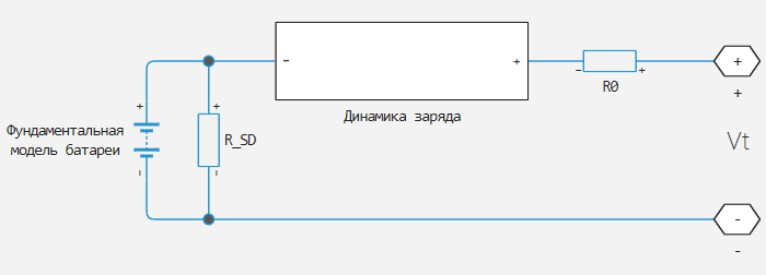
An equivalent battery circuit consists of a fundamental battery model, self-discharge resistance , models of charge dynamics and series resistance .
Battery Model
If for the parameter Battery charge capacity select a value Infinite then the unit will model the battery as a series resistor and a constant voltage source. At the same time, the charge level does not change over time.
If for the parameter Battery charge capacity select a value Finite The unit models the battery as a series resistor and a charge-dependent voltage source. In this case, the voltage is a function of charge and has the following relationship:
where
-
(state of charge) — the ratio of the current charge to the rated capacity of the battery;
-
— The voltage when the battery is fully charged when there is no load (rated voltage). Is set by the parameter Nominal voltage;
-
— this is a coefficient that is calculated so that the battery voltage is when charging . Set the voltage and the cell capacity using the block parameters. — this is a charge when the no-load voltage (open circuit) is equal to , and less than the rated voltage.
The equation defines the approximate relationship between voltage and remaining charge. This approximation reproduces the increasing rate of voltage drop at low charge values and ensures that the battery voltage becomes zero when the charge level is zero. The advantage of this model is that it requires a small number of parameters, which are easily available in most technical data sheets.
Simulation of battery fading
For battery models with finite charge capacity, it is possible to simulate the deterioration of battery performance depending on the number of discharge cycles. This deterioration is called battery fading. To use it, check the box for the parameter Enable fade. This setting opens additional options in the section Fade.
The unit implements battery charge reduction by scaling certain values of the battery parameters that you specify in the section Main, depending on the number of completed discharge cycles. The block uses multipliers , and for parameter values Cell capacity (Ah rating), Internal resistance and Voltage V1 when charge is AH1 accordingly. These multipliers, in turn, depend on the number of discharge cycles.:
where
-
— multiplier for the rated battery capacity;
-
— multiplier for sequential battery resistance;
-
— voltage multiplier ;
-
— the number of discharge cycles performed;
-
— the number of full discharge cycles completed before the start of the simulation;
-
— rated battery capacity in ampere-hours;
-
— instantaneous battery output current;
-
— Heaviside function («The step») for instantaneous battery output current. This function returns
0if the argument is negative, and1if the argument is positive.
The block calculates the coefficients , and by substituting the parameter values specified in the section Fade, into these battery equations. For example, the default set of block parameters corresponds to the following coefficient values:
-
;
-
;
-
.
You can also determine the starting point for the simulation based on the previous charge-discharge history using a high-priority variable. Discharge cycles.
Modeling of thermal effects
If the checkbox for the parameter is selected Enable thermal port In order to determine the behavior of the battery, additional parameters must be set at the second temperature. The extended equations for the voltage when you expose the heat port are as follows:
where
-
— battery temperature;
-
— nominal measurement temperature;
-
— the coefficient of dependence of the parameter on the temperature for ;
-
;
-
— the coefficient of dependence of the parameter on the temperature for ;
-
— calculated in the same way as described in the Battery Model section, using a temperature-modified rated voltage .
Internal series resistance, self-discharge resistance, and any charging-dynamic resistances are also functions of temperature.:
where — the coefficient of dependence of the parameter on temperature.
All temperature dependence coefficients are determined from the corresponding values that you enter for the nominal and second measurement temperatures. If charge dynamics is included in the model, then the time constants change depending on temperature in a similar way.
The battery temperature is determined by summing up all ohmic losses included in the model:
where
-
— thermal mass of the battery;
-
— ohmic loss participant’s number. Depending on the configuration of the unit, the losses may be as follows:
-
consistent resistance;
-
self-discharge resistance;
-
the first segment of charge dynamics;
-
the second segment of charge dynamics;
-
the third segment of charge dynamics;
-
The fourth segment of charge dynamics;
-
The fifth segment of charge dynamics;
-
-
— voltage drop on -m resistance;
-
— - e resistance.
Simulation of charge dynamics
You can simulate the dynamics of battery charge using the parameter Charge dynamics:
-
No dynamics— the equivalent circuit does not contain parallel RC sections. There is no delay between the voltage on the contacts and the internal battery voltage. -
One time-constant dynamics— the equivalent circuit contains one parallel RC section. Specify the time constant using the parameter First time constant. -
Two time-constant dynamics— the equivalent circuit contains two parallel RC sections. Set the time constants using the parameters First time constant and Second time constant. -
Three time-constant dynamics— the equivalent circuit contains three parallel RC sections. Set the time constants using the parameters First time constant, Second time constant and Third time constant. -
Four time-constant dynamics— the equivalent circuit contains four parallel RC sections. Set the time constants using the parameters First time constant, Second time constant, Third time constant and Fourth time constant. -
Five time-constant dynamics— the equivalent circuit contains five parallel RC sections. Specify the time constants using the parameters First time constant, Second time constant, Third time constant, Fourth time constant and Fifth time constant.
This figure shows an equivalent circuit for a unit configured with two time-constant speakers.
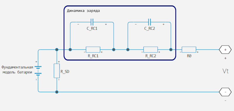
On the diagram:
-
and — parallel RC resistances. Set these values using the parameters First polarization resistance and Second polarization resistance accordingly;
-
and — parallel RC capacitances. The time constant for each parallel section, it connects the values of R and C using the ratio . Ask for each section using the parameters First time constant and Second time constant accordingly;
-
— consistent resistance. Set this value using the parameter Internal resistance.
Simulating battery aging
For battery models with finite charge capacity, it is possible to simulate the degradation of battery performance that occurs when not in use. To do this, check the box for the parameter Calendar aging. Calendar aging affects both internal resistance and capacity. In particular, the increase in resistance depends on various mechanisms, such as the formation of a solid electrolyte interface (SEI) at the anode and cathode and corrosion of the pantograph. These processes mainly depend on the storage temperature, state of charge, and time.
|
Block Battery applies calendar aging only during initialization. When you check the option box Calendar aging, the parameter appears in the block settings Vector of time intervals, which stores the time intervals when the battery was aging before the simulation started. Calendar aging during simulation is not covered by this parameter. |
This equation determines the increase in battery contact resistance as a result of calendar aging.:
where
-
— the open circuit voltage is normalized to the nominal value. Parameter Normalized open-circuit voltage during storage, V/Vnom;
-
— internal resistance. Parameter Internal resistance;
-
— time values obtained from the parameter Vector of time intervals;
-
— temperature values obtained from the parameter Vector of temperatures;
-
— the number of elements in the temperature vector;
-
— linear voltage scale. Parameter Linear scaling for voltage, b;
-
— constant voltage shift. Parameter Constant offset for voltage, c;
-
— exponential increase depending on temperature. Parameter Temperature-dependent exponential increase, d;
-
— time indicator. Parameter Time exponent, a;
-
— electron charge, Cl;
-
— Boltzmann constant, J/K.
Variable R_age_multiplier The Data Inspector stores data on the calendar aging of the battery in contacts with increasing resistance:
For the thermal modeling options of the block, if for the parameter Storage condition the value is set Fixed open-circuit voltage, then you need to specify an additional parameter Open-circuit measurement temperature to convert the voltage of the open storage circuit to a temperature-independent state of charge during storage:
The open circuit voltage, depending on the storage temperature, is determined by this equation:
Finally, this equation determines the increase in the resistance of the battery terminals as a result of calendar aging, depending on the storage temperature.:
Assumptions and limitations
-
It is assumed that the self-discharge resistance does not depend on the number of discharge cycles.
-
For the battery thermal simulation option, you provide attenuation data only for operation at a reference temperature. The block applies the same multipliers , and to the values of the parameters corresponding to the second temperature.
-
When using the heat block simulation options, be careful when operating at temperatures outside the temperature range limited by the parameter values. Measurement temperature and Second measurement temperature. The block uses linear interpolation for the coefficients of the derivatives of the equations, and the simulation results may become non-physical beyond the specified range.
Variables
Use the parameter group Initial Targets to set the priority and initial target values for the block parameter variables before modeling. For more information, see Configuring physical blocks using target values.
Ports
Conserving
#
+
—
positive contact
electricity
Details
The electrical port connected to the positive contact of the battery.
| Program usage name |
|
#
−
—
negative contact
electricity
Details
The electrical port connected to the negative contact of the battery.
| Program usage name |
|
#
H
—
battery thermal port
heat
Details
Thermal port connected to the thermal mass of the battery. When activating this port, specify additional parameters to determine the behavior of the battery. For more information, see Modeling of thermal effects.
Dependencies
To use this port, in the section Thermal Port check the box for the parameter Enable thermal port.
| Program usage name |
|
Output
#
q
—
current battery charge, Kl
scalar
Details
Internal charge in coulombs. Use this output port to change the behavior of the load depending on the charge, without resorting to the complexities of building a charge meter.
Dependencies
To use this port, select the check box for the parameter Expose charge measurement port, and for the parameter Output port type set the value Charge in Coulombs.
| Data types |
|
| Complex numbers support |
I don’t |
#
SOC
—
Battery charge level
scalar
Details
Charge level. Use this output port to change the behavior of the load depending on the level of charge, without resorting to the complexities of building a charge meter.
Charge level is a normalized value equal to the ratio of the current charge to the rated capacity of the battery . The unit evaluates the current battery charge by integrating the output current of the battery terminals. To convert the state of charge to an actual charge, you must use the correct rated capacity of the battery for each temperature.
Dependencies
To use this port, select the check box for the parameter Expose charge measurement port, and for the parameter Output port type set the value SOC.
| Data types |
|
| Complex numbers support |
I don’t |
Parameters
Main
#
Nominal voltage —
Rated output voltage of a fully charged battery
V | uV | mV | kV | MV
Details
The idling voltage of a fully charged battery.
| Units |
|
| Default value |
|
| Program usage name |
|
| Evaluatable |
Yes |
# Current directionality — influence of current direction
Details
If this option is selected, the internal resistance will depend on the current direction.
| Default value |
|
| Program usage name |
|
| Evaluatable |
No |
#
Internal resistance —
internal resistance of the battery
Ohm | mOhm | kOhm | MOhm | GOhm
Details
The resistance of the battery’s internal connections.
Dependencies
To use this option, uncheck the option Current directionality.
| Units |
|
| Default value |
|
| Program usage name |
|
| Evaluatable |
Yes |
#
Internal resistance during discharging —
internal resistance of the battery during discharge
Ohm | mOhm | kOhm | MOhm | GOhm
Details
The internal resistance of the battery during the charging phase.
Dependencies
To use this option, check the box next to Current directionality.
| Units |
|
| Default value |
|
| Program usage name |
|
| Evaluatable |
Yes |
#
Internal resistance during charging —
internal resistance of the battery during charging
Ohm | mOhm | kOhm | MOhm | GOhm
Details
The internal resistance of the battery during the discharge phase.
Dependencies
To use this option, check the box next to Current directionality.
| Units |
|
| Default value |
|
| Program usage name |
|
| Evaluatable |
Yes |
#
Battery charge capacity —
choosing the battery model
Infinite | Finite
Details
Select one of the options for simulating battery capacity:
-
Infinite— Battery voltage is independent of the charge received from the battery, infinite capacity. -
Finite— The battery voltage decreases as the charge decreases.
| Values |
|
| Default value |
|
| Program usage name |
|
| Evaluatable |
No |
#
Cell capacity (Ah rating) —
Rated battery capacity when fully charged
C | nC | uC | mC | nA*s | uA*s | mA*s | A*s | mA*hr | A*hr | kA*hr | MA*hr
Details
The maximum (nominal) battery charge in ampere-hours. To set a target value for the initial battery charge at the beginning of the simulation, use a high-priority variable Charge.
Dependencies
To use this parameter, set for the parameter Battery charge capacity meaning Finite.
| Units |
|
| Default value |
|
| Program usage name |
|
| Evaluatable |
Yes |
#
Voltage V1 when charge is AH1 —
Output voltage at charge level AH1
V | uV | mV | kV | MV
Details
The main output voltage of the battery at the AH1 charge level, as indicated in the parameter Charge AH1 when no-load voltage is V1. This parameter should be less than Nominal voltage.
Dependencies
To use this parameter, set for the parameter Battery charge capacity meaning Finite.
| Units |
|
| Default value |
|
| Program usage name |
|
| Evaluatable |
Yes |
#
Charge AH1 when no-load voltage is V1 —
charge level when the no-load output voltage is V1
C | nC | uC | mC | nA*s | uA*s | mA*s | A*s | mA*hr | A*hr | kA*hr | MA*hr
Details
The battery charge level corresponding to the no-load output voltage set by the parameter Voltage V1 when charge is AH1.
Dependencies
To use this parameter, set for the parameter Battery charge capacity meaning Finite.
| Units |
|
| Default value |
|
| Program usage name |
|
| Evaluatable |
Yes |
# Self-discharge — select whether you want to simulate battery self-discharge.
Details
If this option is selected, the unit simulates battery self-discharge. The unit simulates this effect like a resistor connected to the contacts of a fundamental battery model.
- As the temperature increases, the self-discharge resistance decreases, which leads to an increase in self-discharge. If the resistance decreases too quickly, thermal discharge of the battery and numerical instability may occur. You can solve this problem by doing one of the following
-
-
Reduce thermal resistance.
-
Reduce the gradient of self-discharge resistance depending on the temperature.
-
Increase the self-discharge resistance.
-
Dependencies
To use this parameter, set for the parameter Battery charge capacity meaning Finite.
| Default value |
|
| Program usage name |
|
| Evaluatable |
No |
#
Self-discharge resistance —
resistance reflecting battery self-discharge
Ohm | mOhm | kOhm | MOhm | GOhm
Details
The resistance in the fundamental model of the battery, reflecting the self-discharge of the battery.
Dependencies
To use this option, check the box for the option Self-discharge.
| Units |
|
| Default value |
|
| Program usage name |
|
| Evaluatable |
Yes |
#
Measurement temperature —
the temperature at which the unit parameters are measured
K | degC | degF | degR | deltaK | deltadegC | deltadegF | deltadegR
Details
Temperature , at which the block parameters are measured in the section Main. For more information, see Modeling of thermal effects.
Dependencies
To use this option, check the box for the option Enable thermal port.
| Units |
|
| Default value |
|
| Program usage name |
|
| Evaluatable |
Yes |
# Expose charge measurement port — do I need to open the port to measure the charge
Details
Check the box to open the charge measurement port and measure the internal charge level of the battery.
| Default value |
|
| Program usage name |
|
| Evaluatable |
No |
#
Output port type —
signal selection in the measuring port
Charge in Coulombs | SOC
Details
The parameter has two values:
-
SOC— charge level values are sent to the outputSOC. -
Charge in Coulombs— charge values are sent to the outputqin Pendants.
Dependencies
To use this option, check the box for the option Enable thermal port.
| Values |
|
| Default value |
|
| Program usage name |
|
| Evaluatable |
No |
Dynamics
#
Charge dynamics —
battery charge dynamics model
No dynamics | One time-constant dynamics | Two time-constant dynamics | Three time-constant dynamics | Four time-constant dynamics | Five time-constant dynamics
Details
Choose a method for simulating the dynamics of battery charge. This parameter determines the number of parallel RC sections in the equivalent circuit.:
-
No dynamics— the equivalent circuit does not contain parallel RC sections. There is no delay between the voltage on the contacts and the internal battery voltage. -
One time-constant dynamics— the equivalent circuit contains one parallel RC section. Specify the time constant using the parameter First time constant. -
Two time-constant dynamics— the equivalent circuit contains two parallel RC sections. Set the time constants using the parameters First time constant and Second time constant. -
Three time-constant dynamics— the equivalent circuit contains three parallel RC sections. Set time constants using the First time constant, Second time constant and Third time constant. -
Four time-constant dynamics— the equivalent circuit contains four parallel RC sections. Set the time constants using the parameters First time constant, Second time constant, Third time constant and Fourth time constant. -
Five time-constant dynamics— the equivalent circuit contains five parallel RC sections. Specify the time constants using the parameters First time constant, Second time constant, Third time constant, Fourth time constant and Fifth time constant.
| Values |
|
| Default value |
|
| Program usage name |
|
| Evaluatable |
No |
#
First polarization resistance —
the first RC resistance
Ohm | mOhm | kOhm | MOhm | GOhm
Details
Resistance of the first parallel RC section. This parameter primarily affects the ohmic losses of the RC section.
Dependencies
To use this parameter, set for the parameter Charge dynamics meaning One time-constant dynamics, Two time-constant dynamics, Three time-constant dynamics, Four time-constant dynamics or Five time-constant dynamics.
| Units |
|
| Default value |
|
| Program usage name |
|
| Evaluatable |
Yes |
#
First time constant —
the first time constant is RC
s | ns | us | ms | min | hr | d
Details
The time constant of the first parallel RC section. This value is equal to R*C and affects the dynamics of the RC section.
Dependencies
To use this parameter, set for the parameter Charge dynamics meaning One time-constant dynamics, Two time-constant dynamics, Three time-constant dynamics, Four time-constant dynamics or Five time-constant dynamics.
| Units |
|
| Default value |
|
| Program usage name |
|
| Evaluatable |
Yes |
#
Second polarization resistance —
the second resistance is RC
Ohm | mOhm | kOhm | MOhm | GOhm
Details
Resistance of the second parallel RC section. This parameter primarily affects the ohmic losses of the RC section.
Dependencies
To use this parameter, set for the parameter Charge dynamics meaning Two time-constant dynamics, Three time-constant dynamics, Four time-constant dynamics or Five time-constant dynamics.
| Units |
|
| Default value |
|
| Program usage name |
|
| Evaluatable |
Yes |
#
Second time constant —
the second time constant is RC
s | ns | us | ms | min | hr | d
Details
The time constant of the second parallel RC section. This value is equal to R*C and affects the dynamics of the RC section.
Dependencies
To use this parameter, set for the parameter Charge dynamics meaning Two time-constant dynamics, Three time-constant dynamics, Four time-constant dynamics or Five time-constant dynamics.
| Units |
|
| Default value |
|
| Program usage name |
|
| Evaluatable |
Yes |
#
Third polarization resistance —
The third resistance is RC
Ohm | mOhm | kOhm | MOhm | GOhm
Details
Resistance of the third parallel RC section. This parameter primarily affects the ohmic losses of the RC section.
Dependencies
To use this parameter, set for the parameter Charge dynamics meaning Three time-constant dynamics, Four time-constant dynamics or Five time-constant dynamics.
| Units |
|
| Default value |
|
| Program usage name |
|
| Evaluatable |
Yes |
#
Third time constant —
The third time constant is RC
s | ns | us | ms | min | hr | d
Details
The time constant of the third parallel RC section. This value is equal to R*C and affects the dynamics of the RC section.
Dependencies
To use this parameter, set for the parameter Charge dynamics meaning Three time-constant dynamics, Four time-constant dynamics or Five time-constant dynamics.
| Units |
|
| Default value |
|
| Program usage name |
|
| Evaluatable |
Yes |
#
Fourth polarization resistance —
The fourth resistance is RC
Ohm | mOhm | kOhm | MOhm | GOhm
Details
Resistance of the fourth parallel RC section. This parameter primarily affects the ohmic losses of the RC section.
Dependencies
To use this parameter, set for the parameter Charge dynamics meaning Four time-constant dynamics or Five time-constant dynamics.
| Units |
|
| Default value |
|
| Program usage name |
|
| Evaluatable |
Yes |
#
Fourth time constant —
The fourth time constant is RC
s | ns | us | ms | min | hr | d
Details
The time constant of the fourth parallel RC section. This value is equal to R*C and affects the dynamics of the RC section.
Dependencies
To use this parameter, set for the parameter Charge dynamics meaning Four time-constant dynamics or Five time-constant dynamics.
| Units |
|
| Default value |
|
| Program usage name |
|
| Evaluatable |
Yes |
#
Fifth polarization resistance —
fifth resistance RC
Ohm | mOhm | kOhm | MOhm | GOhm
Details
Resistance of the fifth parallel RC section. This parameter primarily affects the ohmic losses of the RC section.
Dependencies
To use this parameter, set for the parameter Charge dynamics meaning Five time-constant dynamics.
| Units |
|
| Default value |
|
| Program usage name |
|
| Evaluatable |
Yes |
#
Fifth time constant —
The fifth time constant is RC
s | ns | us | ms | min | hr | d
Details
The time constant of the fifth parallel RC section. This value is equal to R*C and affects the dynamics of the RC section.
Dependencies
To use this parameter, set for the parameter Charge dynamics meaning Five time-constant dynamics.
| Units |
|
| Default value |
|
| Program usage name |
|
| Evaluatable |
Yes |
Fade
# Enable fade — select whether you want to simulate battery degradation during charge-discharge
Details
If the box is selected, the unit simulates the battery fading. The characteristics of the battery vary depending on the number of completed charge-discharge cycles. Selecting this option opens additional options in this section that determine the characteristics of the battery after a certain number of discharge cycles. The block uses the values of these parameters to calculate the scale coefficients. , and .
If the checkbox is unchecked, the battery characteristics do not depend on the number of charge-discharge cycles.
For more information, see Simulation of battery fading.
| Default value |
|
| Program usage name |
|
| Evaluatable |
No |
# Number of discharge cycles, N — number of completed charge-discharge cycles
Details
The number of charge-discharge cycles after which the remaining parameters are measured in this section. It defines the scale factors , and , used in simulating battery fading.
Dependencies
To use this option, check the box for the option Enable fade.
| Default value |
|
| Program usage name |
|
| Evaluatable |
Yes |
#
Cell capacity after N discharge cycles —
maximum battery capacity after N discharge cycles
C | nC | uC | mC | nA*s | uA*s | mA*s | A*s | mA*hr | A*hr | kA*hr | MA*hr
Details
Maximum battery charge, in ampere-hours, after the number of discharge cycles set by the parameter Number of discharge cycles, N.
Dependencies
To use this option, check the box for the option Enable fade.
| Units |
|
| Default value |
|
| Program usage name |
|
| Evaluatable |
Yes |
#
Internal resistance after N discharge cycles —
internal resistance of the battery after N discharge cycles
Ohm | mOhm | kOhm | MOhm | GOhm
Details
The internal resistance of the battery after the number of discharge cycles set by the parameter Number of discharge cycles, N.
Dependencies
To use this option, check the box for the option Enable fade, and for the parameter Current directionality in the section Main uncheck the box.
| Units |
|
| Default value |
|
| Program usage name |
|
| Evaluatable |
Yes |
#
Average internal resistance after N discharge cycles —
average internal resistance of the battery after N discharge cycles
Ohm | mOhm | kOhm | MOhm | GOhm
Details
The average value of the battery’s internal resistance during charge and discharge after the number of discharge cycles set by the parameter Number of discharge cycles, N.
Dependencies
To use this option, check the boxes for the option Enable fade and for the parameter Current directionality in the section Main.
| Units |
|
| Default value |
|
| Program usage name |
|
| Evaluatable |
Yes |
#
Voltage V1 at charge AH1 after N discharge cycles —
output voltage at AH1 charge level after N discharge cycles
V | uV | mV | kV | MV
Details
The output voltage of the fundamental battery model at the AH1 charge level after the number of discharge cycles set by the parameter Number of discharge cycles, N.
Dependencies
To use this option, check the box for the option Enable fade.
| Units |
|
| Default value |
|
| Program usage name |
|
| Evaluatable |
Yes |
Calendar Aging
# Calendar aging — the possibility of calendar aging
Details
If this option is selected, the unit uses calendar battery aging.
| Default value |
|
| Program usage name |
|
| Evaluatable |
No |
#
Storage condition —
Storage conditions
Fixed open-circuit voltage | Fixed state of charge
Details
You need to select a parameter that determines the state of charge during storage- the open circuit voltage or the state of charge during storage.
Dependencies
To use this option, check the box for the option Calendar aging.
| Values |
|
| Default value |
|
| Program usage name |
|
| Evaluatable |
No |
# Normalized open-circuit voltage during storage, V/V_nominal — normalized open circuit voltage during storage
Details
Rated open circuit voltage during storage.
Dependencies
To use this option, check the box Calendar aging and for the parameter Storage condition set the value Fixed open-circuit voltage.
| Default value |
|
| Program usage name |
|
| Evaluatable |
Yes |
# State of charge during storage (%) — percentage state of charge during storage
Details
The state of charge during storage, as a percentage.
Dependencies
To use this option, check the box for the option Calendar aging and for the parameter Storage condition meaning Fixed state of charge.
| Default value |
|
| Program usage name |
|
| Evaluatable |
Yes |
#
Open-circuit measurement temperature —
open circuit temperature
K | degC | degF | degR | deltaK | deltadegC | deltadegF | deltadegR
Details
The temperature at which the open circuit voltage was measured.
Dependencies
To use this parameter, open the thermal port of the unit, check the box for the parameter Calendar aging, and for the parameter Storage condition meaning Fixed open-circuit voltage.
| Units |
|
| Default value |
|
| Program usage name |
|
| Evaluatable |
Yes |
#
Vector of time intervals —
vector of time intervals
s | ns | us | ms | min | hr | d
Details
Storage time intervals. This parameter must be equal in size. Vector of temperatures.
Dependencies
To use this option, check the box for the option Calendar aging.
| Units |
|
| Default value |
|
| Program usage name |
|
| Evaluatable |
Yes |
#
Vector of temperatures —
Storage temperatures
K | degC | degF | degR | deltaK | deltadegC | deltadegF | deltadegR
Details
A set of storage temperatures. This parameter must be equal in size. Vector of time intervals.
Dependencies
To use this option, check the box for the option Calendar aging.
| Units |
|
| Default value |
|
| Program usage name |
|
| Evaluatable |
Yes |
# Linear scaling for voltage, b — linear voltage scaling
Details
The linear scaling factor for the open circuit voltage.
Dependencies
To use this option, check the box for the option Calendar aging.
| Default value |
|
| Program usage name |
|
| Evaluatable |
Yes |
# Constant offset for voltage, c — constant voltage shift
Details
Constant offset for the open circuit voltage.
Dependencies
To use this option, check the box for the option Calendar aging.
| Default value |
|
| Program usage name |
|
| Evaluatable |
Yes |
#
Temperature-dependent exponential increase, d —
exponential multiplier of temperature dependence
V | uV | mV | kV | MV
Details
Exponential growth depending on temperature.
Dependencies
To use this option, check the box for the option Calendar aging.
| Units |
|
| Default value |
|
| Program usage name |
|
| Evaluatable |
Yes |
# Time exponent, a — the exponent of time
Details
The exponent multiplier that determines the dependence on time.
Dependencies
To use this option, check the box for the option Calendar aging.
| Default value |
|
| Program usage name |
|
| Evaluatable |
Yes |
Temperature Dependence
#
Nominal voltage at second measurement temperature —
Output voltage when the battery is fully charged
V | uV | mV | kV | MV
Details
The idle voltage on the battery is at the second measurement temperature when it is fully charged.
Dependencies
To use this option, check the box for the option Enable thermal port.
| Units |
|
| Default value |
|
| Program usage name |
|
| Evaluatable |
Yes |
#
Internal resistance at second measurement temperature —
internal resistance of the battery
Ohm | mOhm | kOhm | MOhm | GOhm
Details
The resistance of the battery’s internal connection at the second measurement temperature.
Dependencies
To use this option, check the box for the option Enable thermal port.
| Units |
|
| Default value |
|
| Program usage name |
|
| Evaluatable |
Yes |
#
Internal resistance at second measurement during discharging —
internal resistance of the battery during discharge
Ohm | mOhm | kOhm | MOhm | GOhm
Details
The resistance of the battery’s internal connection at the second measurement temperature during discharge.
Dependencies
To use this option, check the box for the option Enable thermal port.
| Units |
|
| Default value |
|
| Program usage name |
|
| Evaluatable |
Yes |
#
Internal resistance at second measurement during charging —
internal resistance of the battery during charging
Ohm | mOhm | kOhm | MOhm | GOhm
Details
The resistance of the internal connection of the battery at the second measurement temperature during charging.
Dependencies
To use this option, check the box for the option Enable thermal port.
| Units |
|
| Default value |
|
| Program usage name |
|
| Evaluatable |
Yes |
#
Voltage V1 at second measurement temperature —
Output voltage at charge level AH1
V | uV | mV | kV | MV
Details
The output voltage of the main battery model at the temperature of the second measurement and the charge level AH1, set by the parameter AH1 charge at idle voltage V1.
Dependencies
To use this option, check the box for the option Enable thermal port and set for the parameter Battery charge capacity meaning Finite.
| Units |
|
| Default value |
|
| Program usage name |
|
| Evaluatable |
Yes |
#
Self-discharge resistance at second measurement temperature —
resistance reflecting battery self-discharge
Ohm | mOhm | kOhm | MOhm | GOhm
Details
The resistance in the fundamental model of the battery at the second measurement temperature, reflecting the self-discharge of the battery.
Dependencies
To use this option, check the box for the option Enable thermal port and check the box for the parameter Self-discharge.
| Units |
|
| Default value |
|
| Program usage name |
|
| Evaluatable |
Yes |
#
First polarization resistance at second measurement temperature —
The first RC is the resistance at the second measurement temperature
Ohm | mOhm | kOhm | MOhm | GOhm
Details
Resistance of the first parallel RC section at the second measurement temperature.
Dependencies
To use this option, check the box for the option Enable thermal port and set for the parameter Charge dynamics meaning One time-constant dynamics, Two time-constant dynamics, Three time-constant dynamics, Four time-constant dynamics or Five time-constant dynamics.
| Units |
|
| Default value |
|
| Program usage name |
|
| Evaluatable |
Yes |
#
First time constant at second measurement temperature —
the first time constant is RC at the second measurement temperature
s | ns | us | ms | min | hr | d
Details
The time constant of the first parallel RC section at the second measurement temperature.
Dependencies
To use this option, check the box for the option Enable thermal port and set for the parameter Charge dynamics meaning One time-constant dynamics, Two time-constant dynamics, Three time-constant dynamics, Four time-constant dynamics or Five time-constant dynamics.
| Units |
|
| Default value |
|
| Program usage name |
|
| Evaluatable |
Yes |
#
Second polarization resistance at second measurement temperature —
The second RC is the resistance at the second measurement temperature
Ohm | mOhm | kOhm | MOhm | GOhm
Details
Resistance of the second parallel RC section at the second measurement temperature.
Dependencies
To use this option, check the box for the option Enable thermal port and set for the parameter Charge dynamics meaning Two time-constant dynamics, Three time-constant dynamics, Four time-constant dynamics or Five time-constant dynamics.
| Units |
|
| Default value |
|
| Program usage name |
|
| Evaluatable |
Yes |
#
Second time constant at second measurement temperature —
the second time constant is RC at the second measurement temperature
s | ns | us | ms | min | hr | d
Details
The time constant of the second parallel RC section at the second measurement temperature.
Dependencies
To use this option, check the box for the option Enable thermal port and set for the parameter Charge dynamics meaning Two time-constant dynamics, Three time-constant dynamics, Four time-constant dynamics or Five time-constant dynamics.
| Units |
|
| Default value |
|
| Program usage name |
|
| Evaluatable |
Yes |
#
Third polarization resistance at second measurement temperature —
The third RC is the resistance at the second measurement temperature
Ohm | mOhm | kOhm | MOhm | GOhm
Details
Resistance of the third parallel RC section at the second measurement temperature.
Dependencies
To use this option, check the box for the option Enable thermal port and set for the parameter Charge dynamics meaning Three time-constant dynamics, Four time-constant dynamics or Five time-constant dynamics.
| Units |
|
| Default value |
|
| Program usage name |
|
| Evaluatable |
Yes |
#
Third time constant at second measurement temperature —
The third time constant is RC at the second measurement temperature
s | ns | us | ms | min | hr | d
Details
The time constant of the third parallel RC section at the second measurement temperature.
Dependencies
To use this option, check the box for the option Enable thermal port and set for the parameter Charge dynamics meaning Three time-constant dynamics, Four time-constant dynamics or Five time-constant dynamics.
| Units |
|
| Default value |
|
| Program usage name |
|
| Evaluatable |
Yes |
#
Fourth polarization resistance at second measurement temperature —
The fourth RC is the resistance at the second measurement temperature
Ohm | mOhm | kOhm | MOhm | GOhm
Details
Resistance of the fourth parallel RC section at the second measurement temperature.
Dependencies
To use this option, check the box for the option Enable thermal port and set for the parameter Charge dynamics meaning Four time-constant dynamics or Five time-constant dynamics.
| Units |
|
| Default value |
|
| Program usage name |
|
| Evaluatable |
Yes |
#
Fourth time constant at second measurement temperature —
the fourth time constant is RC at the second measurement temperature
s | ns | us | ms | min | hr | d
Details
The time constant of the fourth parallel RC section at the second measurement temperature.
Dependencies
To use this option, check the box for the option Enable thermal port and set for the parameter Charge dynamics meaning Four time-constant dynamics or Five time-constant dynamics.
| Units |
|
| Default value |
|
| Program usage name |
|
| Evaluatable |
Yes |
#
Fifth polarization resistance at second measurement temperature —
The fifth RC is the resistance at the second measurement temperature
Ohm | mOhm | kOhm | MOhm | GOhm
Details
Resistance of the fifth parallel RC section at the second measurement temperature.
Dependencies
To use this option, check the box for the option Enable thermal port and set for the parameter Charge dynamics meaning Five time-constant dynamics.
| Units |
|
| Default value |
|
| Program usage name |
|
| Evaluatable |
Yes |
#
Fifth time constant at second measurement temperature —
the fifth time constant is RC at the second measurement temperature
s | ns | us | ms | min | hr | d
Details
The time constant of the fifth parallel RC section at the second measurement temperature.
Dependencies
To use this option, check the box for the option Enable thermal port and set for the parameter Charge dynamics meaning Five time-constant dynamics.
| Units |
|
| Default value |
|
| Program usage name |
|
| Evaluatable |
Yes |
#
Second measurement temperature —
the temperature at which the unit parameters are measured
K | degC | degF | degR | deltaK | deltadegC | deltadegF | deltadegR
Details
Temperature , at which the block parameters are measured in the section Temperature Dependence.
Dependencies
To use this option, check the box for the option Enable thermal port.
| Units |
|
| Default value |
|
| Program usage name |
|
| Evaluatable |
Yes |
Thermal Port
# Enable thermal port — turning on the heat port
Details
Select this option to enable the thermal port of the unit and simulate the thermal effects of the battery.
| Default value |
|
| Program usage name |
|
| Evaluatable |
No |
#
Thermal mass —
the heat capacity associated with the thermal port
J/K | kJ/K
Details
The heat capacity associated with the thermal port H. It represents the energy needed to increase the temperature of the heating port by one degree.
Dependencies
To use this option, check the box for the option Enable thermal port.
| Units |
|
| Default value |
|
| Program usage name |
|
| Evaluatable |
Yes |
Literature
-
Ramadass, P., B. Haran, R. E. White, and B. N. Popov. “Mathematical modeling of the capacity fade of Li-ion cells.” Journal of Power Sources. 123 (2003), pp. 230–240.
-
Ning, G., B. Haran, and B. N. Popov. “Capacity fade study of lithium-ion batteries cycled at high discharge rates.” Journal of Power Sources. 117 (2003), pp. 160–169.