Fuel Cell
The electrical system of the fuel cell.
blockType: AcausalElectricPowerSystems.Sources.FuelCell
|
Path in the library: |

Description
Block Fuel Cell simulates a fuel cell that converts the chemical energy of hydrogen into electrical energy.
This chemical reaction determines the electrical transformation.:
The chemical reaction occurs as a result of the following anodic and cathodic half reactions:

Block Fuel Cell It consists of several fuel cells connected in series. An equivalent circuit of one of the block elements is shown below:
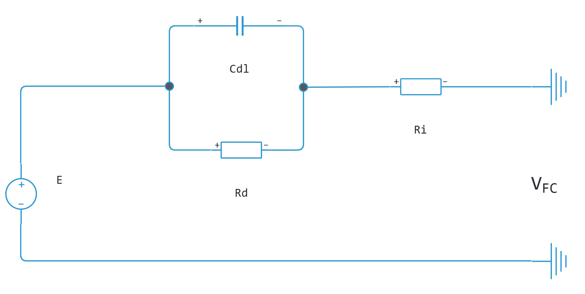
where
-
– cell voltage;
-
– corresponds to the parameter Internal resistance;
-
– corresponds to the parameter Sum of activation and concentration resistance;
-
– parallel RC capacitance, which takes into account the dynamics of time in the cell.
The equations
Use the parameter Model fidelity to allow one of two levels of simulation accuracy Fuel Cell:
-
Simplified - nominal conditions– The unit calculates the Nernst voltage under nominal temperature and pressure conditions. -
Detailed with signal inputs– the unit calculates the Nernst voltage, taking into account the pressure and consumption of fuel and air.
The simplified electrical model
If for the parameter Model fidelity the value is set Simplified - nominal conditions, block Fuel Cell calculates the Nernst voltage, , under nominal temperature and pressure conditions, according to the equations:
where
-
– corresponds to the value of the parameter Open-circuit voltage;
-
– corresponds to the value of the parameter Number of cells per module;
-
– the current generated by the fuel cell;
-
– voltage at the terminals of the fuel cell;
-
– corresponds to the value of the parameter Module units (Series);
-
– voltage drop that takes into account the dynamics of the fuel cell;
-
– corresponds to the value of the parameter Tafel slope, in volts;
-
– corresponds to the value of the parameter Nominal exchange current;
-
.
The detailed electrical model
If for the parameter Model fidelity the value is set Detailed with signal inputs, the fuel cell unit calculates the Nernst voltage, considering the pressure and fuel and air consumption.
In this mode, the rate of hydrogen utilization is, , and oxygen, , are defined by the equations:
where
-
– thermal stress at room temperature;
-
– fuel supply pressure in bar;
-
– fuel consumption;
-
– the concentration of hydrogen in the fuel, as a percentage;
-
– air supply pressure in bar;
-
– air consumption;
-
– oxygen concentration in the air, as a percentage.
The partial pressure values are determined by the equations:
where – the concentration of vapors in the air, in percent.
The block then calculates the Nernst voltage as:
where
-
;
-
– electrokinetic member for activation;
-
– electrokinetic member for concentration;
-
;
-
– constant voltage at the rated operating mode;
-
– the operating temperature of the fuel cell;
-
– corresponds to the value of the parameter Nominal temperature;
-
– the number of moving electrons per second;
-
– the number of moving electrons per second for a given parameter value Nominal exchange current;
-
– Faraday’s constant;
-
– universal gas constant;
-
– nominal pressure of hydrogen in bar;
-
– nominal oxygen pressure in bar;
-
– Taffeta tilt depending on temperature;
-
– corresponds to the value of the parameter Collapse current;
-
Voltage
1.229represents the standard cell potential for the Nernst equation.
The unit calculates the power dissipation or heat generated in a fuel cell using the following equation:
where
-
– the total velocity of electron circulation in mol/s;
-
– change in the entropy of the fuel cell reaction in kJ/(mol⋅s) at the operating temperature of the fuel cell;
-
– the change in the Gibbs free energy of the total reaction of the fuel cell in kJ/mol at the operating temperature of the fuel cell.
Variables
Use the parameter group Initial Targets to set the priority and initial target values for the block parameter variables before modeling. For more information, see Configuring physical blocks using target values.
Ports
Conserving
#
+
—
favourable
electricity
Details
A non-directional port representing the positive terminal of the fuel cell.
| Program usage name |
|
#
-
—
negative
electricity
Details
A non-directional port representing the negative terminal of the fuel cell.
| Program usage name |
|
#
H
—
heat port
heat
Details
Heat port.
Dependencies
To use this port, set the parameters Model fidelity to Detailed with signal inputs.
| Program usage name |
|
Input
#
pfuel
—
absolute pressure of fuel supply, Pa
scalar
Details
Input port that defines the absolute pressure of the fuel supplied to the unit in Pa.
Dependencies
To use this port, set the parameter Model fidelity to the value of Detailed with signal inputs.
| Data types |
|
| Complex numbers support |
No |
#
pair
—
air overpressure, Pa
scalar
Details
An input port that determines the gauge air pressure in Pa.
Dependencies
To use this port, set the parameter Model fidelity to the value of Detailed with signal inputs.
| Data types |
|
| Complex numbers support |
No |
#
qfuel
—
fuel consumption, m3/s
scalar
Details
An input port that defines the volumetric fuel flow rate of the unit in m3/c.
Dependencies
To use this port, set the parameter Model fidelity to Detailed with signal inputs.
| Data types |
|
| Complex numbers support |
No |
#
qair
—
air flow rate, m3/s
scalar
Details
An input port that defines the air flow rate of the unit in m3/s.
Dependencies
To use this port, set the parameters Model fidelity to Detailed with signal inputs.
| Data types |
|
| Complex numbers support |
No |
Parameters
Main
#
Model fidelity —
accuracy of the fuel cell model
Simplified - nominal conditions | Detailed with signal inputs
Details
The level of accuracy of the fuel cell model.
| Values |
|
| Default value |
|
| Program usage name |
|
| Evaluatable |
No |
#
Open-circuit voltage —
open circuit voltage
V | uV | mV | kV | MV
Details
Open circuit voltage.
If the flow is low or close to zero and the fuel and air pressures are nominal, the fuel cell output voltage is equal to the open circuit voltage multiplied by the number of module units. The current flowing out of the fuel cell is negligible.
| Units |
|
| Default value |
|
| Program usage name |
|
| Evaluatable |
Yes |
#
Tafel slope —
Tafel slope
V | uV | mV | kV | MV
Details
The amount of excess potential required to increase the reaction rate by a factor of ten.
| Units |
|
| Default value |
|
| Program usage name |
|
| Evaluatable |
Yes |
#
Internal resistance —
internal resistance
Ohm | mOhm | kOhm | MOhm | GOhm
Details
Internal resistance.
| Units |
|
| Default value |
|
| Program usage name |
|
| Evaluatable |
Yes |
#
Nominal exchange current —
rated exchange current
A | pA | nA | uA | mA | kA | MA
Details
Exchange current at rated temperature.
At the nominal exchange current, the fuel cell leaves the activation polarisation region and enters the ohmic polarisation region.
| Units |
|
| Default value |
|
| Program usage name |
|
| Evaluatable |
Yes |
#
Collapse current —
collapse current
A | pA | nA | uA | mA | kA | MA
Details
The value of current at which the voltage across the fuel cell becomes zero. When the fuel cell enters the region of concentration polarisation and the current continues to rise, the voltage starts to drop faster.
Dependencies
To use this parameter, set the parameter Model fidelity to the value of Detailed with signal inputs.
| Units |
|
| Default value |
|
| Program usage name |
|
| Evaluatable |
Yes |
# Number of cells per module — number of cells per module
Details
Number of cells per module.
The value of the number of cells in this block corresponds to the fuel cell delivering the maximum power output for the given flow and pressure values .
| Default value |
|
| Program usage name |
|
| Evaluatable |
Yes |
# Module units (Series) — stack of modules in series
Details
A stack of modules connected in series.
Connecting modules in series to increase the voltage. For example, 10 modules connected in series with an open circuit voltage of 65 V produce a voltage of 650 V.
| Default value |
|
| Program usage name |
|
| Evaluatable |
Yes |
Supply
#
Nominal H2 pressure —
nominal hydrogen pressure
Pa | uPa | hPa | kPa | MPa | GPa | kgf/m^2 | kgf/cm^2 | kgf/mm^2 | mbar | bar | kbar | atm | ksi | psi | mmHg | inHg
Details
Excess hydrogen pressure at nominal temperature.
Dependencies
To use this parameter, set the parameters Model fidelity to . Detailed with signal inputs.
| Units |
|
| Default value |
|
| Program usage name |
|
| Evaluatable |
Yes |
#
Nominal O2 pressure —
nominal oxygen pressure
Pa | uPa | hPa | kPa | MPa | GPa | kgf/m^2 | kgf/cm^2 | kgf/mm^2 | mbar | bar | kbar | atm | ksi | psi | mmHg | inHg
Details
Oxygen overpressure at rated temperature.
Dependencies
To use this parameter, set the parameters Model fidelity to . Detailed with signal inputs.
| Units |
|
| Default value |
|
| Program usage name |
|
| Evaluatable |
Yes |
# Concentration H2 in fuel (%) — hydrogen concentration in fuel
Details
Molar concentration of hydrogen in fuel.
The unit of measurement is per cent.
Dependencies
To use this parameter, set the Model fidelity parameters to . Detailed with signal inputs.
| Default value |
|
| Program usage name |
|
| Evaluatable |
Yes |
# Concentration O2 in air (%) — fuel oxygen concentration
Details
Molar concentration of oxygen in fuel.
The units of measurement are per cent.
Dependencies
To use this parameter, set the Model fidelity parameters to . Detailed with signal inputs.
| Default value |
|
| Program usage name |
|
| Evaluatable |
Yes |
# Concentration vapor in air (%) — airborne vapour concentration
Details
Molar concentration of vapours in air.
The unit of measurement is per cent.
Dependencies
To use this parameter, set the Model fidelity parameters to . Detailed with signal inputs.
| Default value |
|
| Program usage name |
|
| Evaluatable |
Yes |
Dynamics
# Model activation delay — activation delay modelling option
Details
Check this parameter if you want to model the activation delay of the fuel cell.
| Default value |
|
| Program usage name |
|
| Evaluatable |
No |
#
Sum of activation and concentration resistance —
sum of activation and concentration resistance
Ohm | mOhm | kOhm | MOhm | GOhm
Details
The sum of activation resistance and concentration resistance.
Dependencies
To use this parameter, select the checkbox Model activation delay.
| Units |
|
| Default value |
|
| Program usage name |
|
| Evaluatable |
Yes |
#
Time constant —
time constant
s | ns | us | ms | min | hr | d
Details
Time constant.
Dependencies
To use this parameter, select the check box Model activation delay.
| Units |
|
| Default value |
|
| Program usage name |
|
| Evaluatable |
Yes |
Thermal
#
Nominal temperature —
nominal temperature
K | degC | degF | degR | deltaK | deltadegC | deltadegF | deltadegR
Details
The temperature at which the nominal parameters are measured.
Dependencies
To use this parameter, set the parameters Model fidelity to . Detailed with signal inputs.
| Units |
|
| Default value |
|
| Program usage name |
|
| Evaluatable |
Yes |
#
Thermal mass —
thermal mass associated with the heat port
J/K | kJ/K
Details
Thermal mass associated with the heat port H.
This value represents the energy required to raise the temperature of the heat port by one degree.
Dependencies
To use this parameter, set the Model fidelity parameters to Detailed with signal inputs.
| Units |
|
| Default value |
|
| Program usage name |
|
| Evaluatable |
Yes |