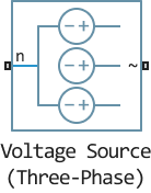
Voltage Source (Three-Phase)
Ideal three-phase voltage source with additional harmonics.
blockType: AcausalElectricPowerSystems.Sources.ThreePhaseVoltage
|
Path in the library: |
Description
The Voltage Source (Three-Phase) block simulates either an ideal three-phase voltage source or a three-phase voltage source with additional harmonics. The configuration is set by the Source harmonics parameter.
If Source Impedance is set to `None', the Voltage Source (Three-Phase) unit simulates an ideal three-phase voltage source that maintains a sinusoidal voltage of the specified magnitude at its terminals, regardless of the current flowing through it.
The source is star connected, with port n corresponding to the neutral. Port ~ is a three-phase port representing the three phases: a, b, and c. The current is positive if it flows from neutral to phase, and the voltage on each phase is equal to the difference between the terminal voltage and the neutral voltage, .
Equations
The output voltage is defined by the following equations:
,
Where:
- is the amplitude phase voltage.
, , are the corresponding phase voltages.
- frequency.
- phase shift.
- time.
In the case of a three-phase voltage source with additional harmonics, the output voltage is determined by the following equations:
,
Where:
- is a line vector containing the amplitude voltages of the fundamental and higher harmonics.
- RMS (root mean square) line voltage.
- vector-string of harmonic coefficients. The first element is equal to 1, which corresponds to the fundamental harmonic.
- vector-string of harmonic numbers. The first element is equal to 1, which corresponds to the main harmonic.
, , - corresponding phase voltages.
- vector-column of harmonic frequencies. The first element is the fundamental frequency.
- vector-column of phase shifts of harmonics. The first element is the phase shift of the main harmonic.
- vector-column of harmonic phase shifts. The first element is 120°.
- time.
When X/R ratio is selected for the *Source Impedance parameter, the equations for the source impedance are as follows:
,
Where:
- the specified short-circuit power level.
- the specified source X/R ratio.
- the design impedance of the source.
- calculated source reactance.
- calculated inductance of the source.
Parameters
Main
Rated voltage (phase-to-phase RMS), V - rms linear voltage
sqrt(2) V (by default) | sqrt(3) * 100
RMS linear (phase-to-phase) voltage.
Phase shift, deg - phase shift
`0.0 (by default).
Phase shift in angular units.
Frequency, Hz - current frequency
50.0 Hz (By default).
Current frequency.
Source impedance - source impedance setting method
X/R (by default) | None | Series R | Series L | Series RL
Specifies the method of setting the source impedance. By default, the option is X/R Ratio.
Options:
-
None. -
`X/R
-
`Series R
-
`Series L
-
`Series RL
Short-circuit power level, V*A - short-circuit power level.
1e6 V*A (By default)
Short-circuit power level.
Source X/R ratio - the ratio of reactive to active resistance
15 (By default)
Complex resistance, i.e. the ratio of reactive resistance to active resistance.
R, Ohm - source resistance
0.01 Ohm (by default)
Ohmic resistance of the source.
L, H - source inductance
3.97e-4 Gn (by default)
Source inductance.
Harmonics
Source harmonics - generation of higher harmonics
None (by default) | Generate
None - no higher harmonics, Generate - added to the source harmonics. The value by default is None.
Harmonic orders - harmonic orders
[5, 7, 11, 13] (By default).
Vector-string of orders of higher harmonics; positive integers.
Harmonic magnitude to peak magnitude ratios - ratios of the amplitudes of the higher harmonics to the amplitude of the main harmonic
[0.1,0.1,0.1,0.1,0.1] (by default)
Vector-string of ratios of amplitudes of higher harmonics to the amplitude of the main one.
