Grounding of the transformer's neutral conductor
Description of the model
This example examines the effect of grounding the neutral conductors of transformers (TP) and turning on the reactors in the neutral conductors of TP on the magnitude of the single-phase short-circuit current to earth. The model is a 110 kV CHP switchgear with six 50 MW generators, from where electricity is transmitted through two 50 km long double-circuit overhead lines to the power grid. At a time of 0.5 s, a single-phase short circuit to earth with a duration of 0.5 s occurs on the 110 kV bus.
The main purpose of limiting single-phase short-circuit currents is to bring their values in line with acceptable ones and increase the reliability of the equipment. The following scenarios are considered for comparing the main methods of limiting the currents of single-phase short circuits [1-3]:
1) The neutral conductors of all TRS are grounded;
2) The neutrals of only two TP are grounded, the other four are grounded;
3) Reactors are included in all neutral conductors of the TP.
It also shows the process of launching and configuring the model from the script development environment using command control, processing simulation results, visualizing simulation results, and offers scenarios for working with the model independently. The values of currents and voltages are logged, and their time schedules are shown. The model is configured for each of the scenarios by changing the positions of the switches in the "Grounding" subsystems connected to the neutral terminals of the TP. The model's appearance:
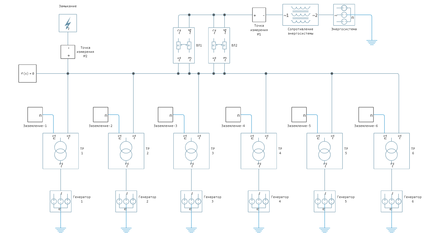
The power system and generators are modeled by the block Voltage Source (Three-Phase), the steady-state mode is set by setting the current line voltage and phase shift. The resistances of the direct and zero sequence of the power system are modeled by the block Coupled Lines (Three-Phase). A short circuit is modeled by a block Fault (Three-Phase) in the settings of this block, using the Failure mode drop-down menu, you can select the type of short circuit. Transformers are modeled by a block Two-Winding Transformer (Three-Phase). Overhead lines are modeled by a block Double-Circuit Transmission Line, which is a U-shaped substitution scheme taking into account the mutual induction between the chains. System parameters:
| Element | Parameter |
|---|---|
| The power system | Equivalent EMF |
| Generators 1-6 | Equivalent EMF |
| VL 1,2 | AC 240/32 |
| TR 1-6 | TD-63000/110 |
Experience in grounding all neutral conductors of the TR
Importing the necessary module for working with LaTeX graphs and strings:
using Plots
gr()
Loading the model:
model_name = "grounded_neutral_network_effect";
model_name in [m.name for m in engee.get_all_models()] ? engee.open(model_name) : engee.load( "$(@__DIR__)/$(model_name).engee");
Setting up the model for the first experiment when grounding all neutral conductors of the TP is carried out by changing the values of the blocks of constants connected to the switches. If the value of the constant is zero, then the switch is in a closed state, otherwise it opens. Thus, to ground the neutral conductors of the TP, the following constants must be set:
# Short circuit of all neutrals to ground
for i in 1:6
    engee.set_param!(model_name*"/Заземление-"*string(i)*"/Constant "*string(i), "Value" => 0);
    engee.set_param!(model_name*"/Заземление-"*string(i)*"/Constant_ react-"*string(i), "Value" => 1);
end
Launching the uploaded model:
results = engee.run(model_name);
To import the simulation results, logging of the necessary signals was enabled in advance and their names were set. We convert the instantaneous values of currents and voltages of the results variable into separate vectors:
# simulation time vector
sim_time = results["i_a_kz"].time;
# current at the short circuit location
i_fault = hcat(results["i_a_kz"].value,results["i_b_kz"].value,results["i_c_kz"].value);
# neutral voltage TR 6
Un = results["Un"].value;
# phase B voltage at the short circuit location
v_b_kz = results["v_b_kz"].value;
Graph of short-circuit currents at the fault location at the measuring point 2:
plot(sim_time, i_fault./1e3, label = [L"I_a" L"I_b" L"I_c"], title = "Short circuit currents",
linecolor = [:orange :green :red], ylabel = "I, kA", xlabel="Time, c", size = (700,440))
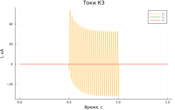
println("Shock current = "*string(round(maximum(i_fault)))*" But")
print("The current value of the periodic component = "*string(round(maximum(i_fault[8000:10000,:])/sqrt(2)))*" But")
When all the neutral conductors of the transformers were grounded, the values of the single-phase short-circuit currents turned out to be quite large. It is advisable to apply measures to reduce these values to reduce the wear of switches and overload of equipment. For this purpose, partial grounding of the TP neutrals can be applied, which will lead to an increase in the total network resistance along the zero sequence and a decrease in single-phase short-circuit currents. The advantage of grounding all neutral conductors is the absence of overvoltages on the neutral conductors and undamaged phases.
Experience with the grounding of four neutral conductors:
The model is adjusted for the experiment when four neutral conductors of the TP are grounded by changing the values of the constant blocks connected to the switches. To ground the neutral conductors of the TP, the following constants must be set:
# grounding a part of the neutral conductors
for (i,j) in zip(1:6,[0 0 1 1 1 1])
    engee.set_param!(model_name*"/Заземление-"*string(i)*"/Constant "*string(i), "Value" => j);
    engee.set_param!(model_name*"/Заземление-"*string(i)*"/Constant_ react-"*string(i), "Value" => 1);
end
Running the loaded model and importing the results:
results = engee.run(model_name);
# simulation time vector
sim_time = results["i_a_kz"].time;
# current at the short circuit location
i_fault = hcat(results["i_a_kz"].value,results["i_b_kz"].value,results["i_c_kz"].value);
# neutral voltage TR 6
Un = results["Un"].value;
# phase B voltage at the short-circuit location
v_b_kz = results["v_b_kz"].value;
Graph of short-circuit currents at the fault location at the measuring point 2:
plot(sim_time, i_fault./1e3, label = [L"I_a" L"I_b" L"I_c"], linecolor = [:orange :green :red],
title = "Short circuit currents", ylabel = "I, kA", xlabel="Time, c", size = (700,440))
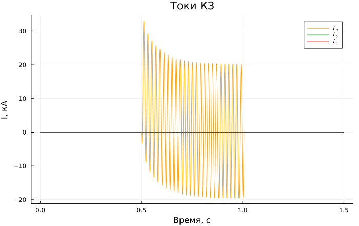
println("Shock current = "*string(round(maximum(i_fault)))*" But")
print("The active peroidal component = "*string(round(maximum(i_fault[8000:10000,:])/sqrt(2)))*" But")
Due to the grounding of the neutrals of the four TP, it was possible to reduce the values of the short-circuit currents by about 1.5 times.
Voltage graph between ground and neutral TR 6:
plot(sim_time, Un./1e3, label = L"U_n", title = "Neutral voltage", ylabel = "U, kV", xlabel="Time, c", size = (700,440))
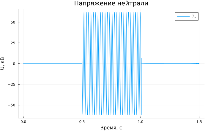
println("The current voltage on the neutral = "*string(round(maximum(Un)/sqrt(2)))*" In")
println("Earth fault coefficient = "*string(round(maximum(v_b_kz)/(110e3*sqrt(2/3)),digits=3)))
The reverse side of the partial grounding of the TP neutrals is the appearance of voltage on the grounded neutrals. It is necessary to take this fact into account when choosing measures to limit the currents of single-phase short circuits and to prevent exceeding the long-term permissible levels of industrial frequency voltages on neutral conductors. Grounding through reactors can be used to reduce the voltage values on the neutral conductors of the TP. Another problem is the voltage increase of the intact phases (in this example, phases B and C). The value of the earth fault coefficient has a value greater than 1.4, which is unacceptable due to the operating conditions of valve arresters and OPN.
Experience in grounding all TP through reactors
Reactors with an inductive resistance of 10 ohms were selected for block TP. Setting up the model for the experiment when grounding the neutral conductors of the TP through the reactors is carried out by changing the values of the constant blocks connected to the switches. To connect the reactors, the following constants must be set:
# connection of reactors
for i in 1:6
    engee.set_param!(model_name*"/Заземление-"*string(i)*"/Constant "*string(i), "Value" => 1);
    engee.set_param!(model_name*"/Заземление-"*string(i)*"/Constant_ react-"*string(i), "Value" => 0);
end
Running the loaded model and importing the results:
results = engee.run(model_name);
# simulation time vector
sim_time = results["i_a_kz"].time;
# current at the short circuit location
i_fault = hcat(results["i_a_kz"].value,results["i_b_kz"].value,results["i_c_kz"].value);
# neutral voltage TR 6
Un = results["Un"].value;
# phase B voltage at the short circuit location
v_b_kz = results["v_b_kz"].value;
Graph of the short-circuit current at the fault location at the measuring point 2:
plot(sim_time, i_fault./1e3, label = [L"I_a" L"I_b" L"I_c"], title = "Short circuit currents",
linecolor = [:orange :green :red], ylabel = "I, kA", xlabel="Time, c", size = (700,440))
Voltage graph between ground and neutral TR 6:
plot(sim_time, Un./1e3, label = L"U_n", title = "Neutral voltage", ylabel = "U, kV", xlabel="Time, c", size = (700,440))
println("The current voltage on the neutral = "*string(round(maximum(Un)/sqrt(2)))*" In")
println("Earth fault coefficient = "*string(round(maximum(v_b_kz)/(110e3*sqrt(2/3)),digits=3)))
Connecting the reactors to the neutral conductor leads to an increase in the total resistance of the zero sequence relative to the short-circuit location, thereby reducing the values of single-phase short-circuit currents. Compared with partial grounding of the TP neutrals, this method made it possible, with a slight increase in the values of short-circuit currents, to significantly reduce overvoltages on the neutral and undamaged phases.
Addition
Try to change the following model parameters yourself and explore how this affects the simulation results:
- reduce and increase the overhead line length by 25 km;
- the number of grounded neutral conductors TR;
- Double the resistance of the reactors.
Conclusions
In this example, tools were used for command management of the Engee model and uploading simulation results, and work with the Plots module is shown. The measured currents and voltages were imported into the Workspace from the result variable, then displayed on time graphs and as text. The effect on single-phase short-circuit currents of grounding the neutral conductors and switching on the reactors in them is shown and analyzed.
The use of reactors in neutral TP turned out to be the most effective in terms of reducing single-phase short-circuit currents and limiting overvoltages on neutral and undamaged phases. However, this measure requires additional capital and operating costs, therefore, when choosing a method for limiting single-phase short-circuit currents, each case must be considered individually, taking into account all the features of the network circuit, equipment characteristics and regulatory requirements.
Links
- RD 34.20.176. Guidelines for limiting single-phase short-circuit currents in 110 - 220 kV electrical networks of power systems" (approved by the USSR Ministry of Energy on 10.12.1984) URL: https://meganorm.ru/Data2/1/4294817/4294817287.htm (accessed 02.12.2024)
- ONE HUNDRED 34.01-21.1-001-2017 . Distribution electric networks with a voltage of 0.4-110 kV. Requirements for technological design. URL: https://www.rosseti.ru/upload/iblock/c59/3yblo2sg3d5w1jd1qzun11h05ypjx66f/СТО 34.01-21.1-001-2017v2022.pdf (accessed 09.12.2024)
- Order No. 6 of the Ministry of Energy of the Russian Federation dated
01/15/2024 "On Approval of Methodological Guidelines for the Technological Design of alternating current substations with a higher voltage of 35 - 750 kV". URL: http://publication.pravo.gov.ru/document/0001202407020008 (accessed 09.12.2024)