Calculation of power grid modes
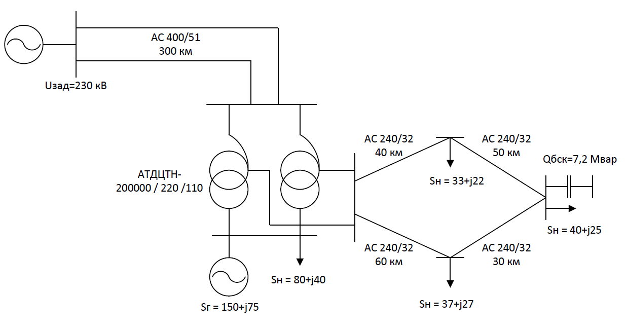
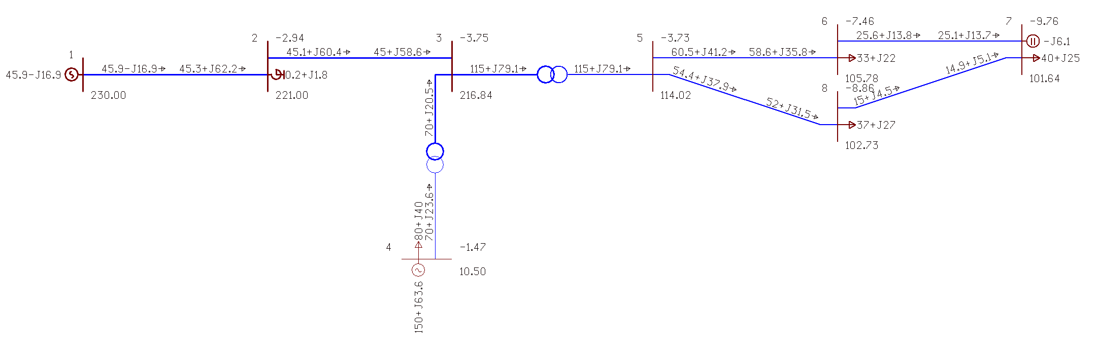
This example shows how to use the application Calculation of power grid modes using the example of the power system shown in the figure:
To enter the scheme into the application and calculate the mode, a number of sequential actions must be performed.
1. Drawing up a replacement scheme
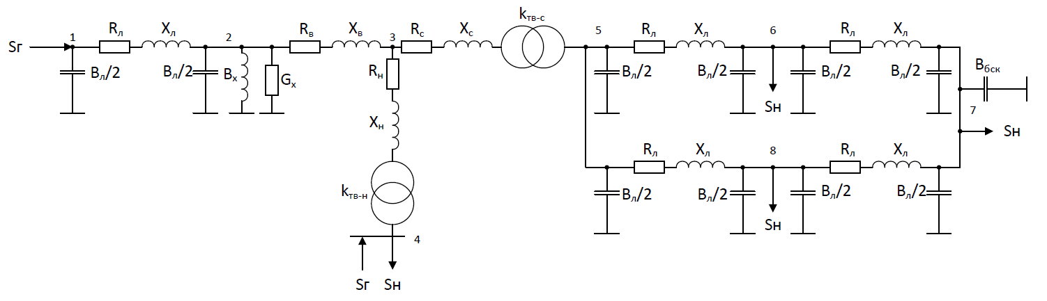
To correctly set the scheme in the application, you should first create a replacement scheme with numbering of all nodes. Loads and generators are set by power injection, overhead lines (overhead lines) are modeled according to the Π-substitution scheme, autotransformers (AT) are represented according to the "star" scheme with an intermediate node and three branches, two of which have transformation coefficients, static capacitor banks (STCS) are replaced by a shunt.
2. Calculation of the parameters of the substitution scheme
Formulas for calculating the parameters of substitution schemes for elements of the power system.
VL:
Active resistance:
Inductive resistance:
Capacitive earth conduction:
The calculations are summarized in a table:
| The \VL parameter | 1-2 | 5-6 | 6-7 | 7-8 | 5-8 |
|---|---|---|---|---|---|
| Wire brand | AC 400/51 | AC 240/32 | AC 240/32 | AC 240/32 | AC 240/32 |
| 220 | 110 | 110 | 110 | 110 | |
| 0.0730 | 0.118 | 0.118 | 0.118 | 0.118 | |
| 0.42 | 0.405 | 0.405 | 0.405 | 0.405 | |
| 2.701 | 2.808 | 2.808 | 2.808 | 2.808 | |
| 300 | 40 | 50 | 30 | 60 | |
| 2 | 1 | 1 | 1 | 1 | |
| 10.95 | 4.72 | 5.9 | 3.54 | 7.08 | |
| 63 | 16.2 | 20.25 | 12.15 | 24.3 | |
| 1620.6 | 112.32 | 140.4 | 84.24 | 168.48 |
AT:
The active resistances are calculated taking into account the winding capacities in:C:N = 100%:100%:50%:< br>
Recalculation of short-circuit voltages:
Because it cannot be physically negative, so we accept it as zero.
Inductive resistances:
Active and inductive conductivities of the magnetization branch AT:
Transformation coefficients:
BSK:
3. Setting the schema in the application
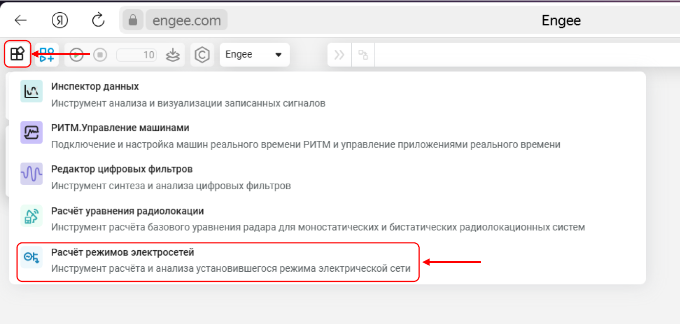
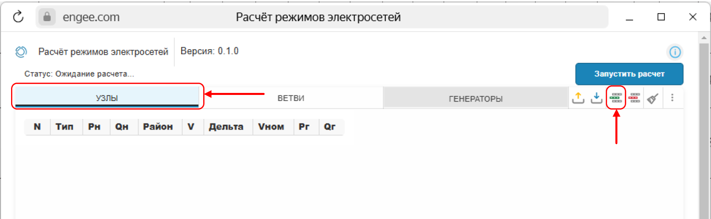
To open the application, go to the Engee workspace and select Calculation of power grid modes in the upper-left corner of the Applications section.
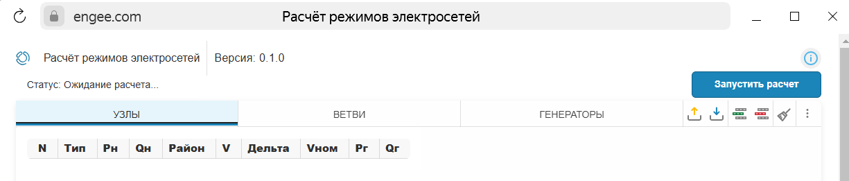
To work with the application, three tabs with tables are used: Nodes, Branches, and Generators. They will be empty when the application is opened. All three tables have a row number column N, which must be filled in when each row is added.
Nodes
Let's start by defining the nodes. To add a node, select the Nodes tab and click the Add Row button.
Node No. 1 is the base node, for it it is necessary to set the rated voltage, type and add a generator to this node on the Generators tab. The generator has columns for the node number Nnode = 1 and the set voltage Vhd = 230 kV.
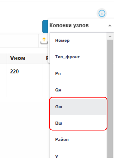
Node No. 2 is a load node, it is necessary to specify the type, rated voltage and conductivity of the shunt of the transverse branch of the autotransformer. The active and capacitive conductivities of the shunt are set with a plus sign, and the inductive with a minus sign. By default, there are no shunt conduction columns on the Nodes tab. To add columns, click Configure visible columns -> Node Columns -> Gw, Bw.
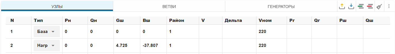
After adding the columns, we enter the conductivity values, it should look like in the figure:
Node No. 3 is also a load unit, we enter the type and rated voltage.
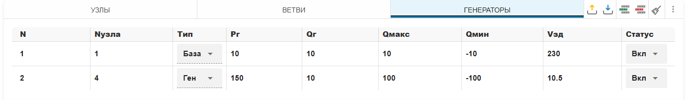
Node No. 4 — the load, the type of "generator" and the rated voltage of 10 kV are set for it. The load capacity is set in columns Ph = 80 MW and Qh = 40 Mvar. The generator's columns have node numbers Nnode = 4, active power Rg = 150 MW, set voltage Vhd = 10.5 kV and reactive power control limits Qmax = 100 Mvar and Qmin = -100 Mvar.
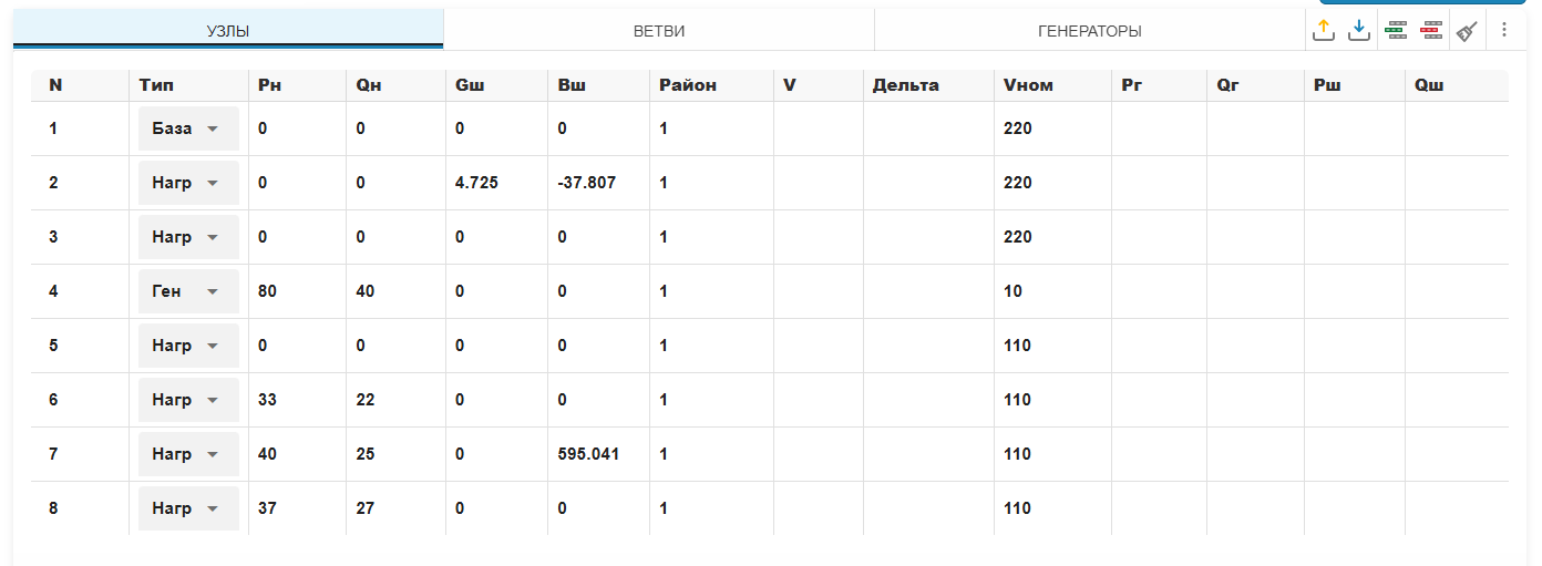
Nodes No. 5-8 are load nodes, in node No. 7 it is necessary to set a BSC in the form of a shunt.
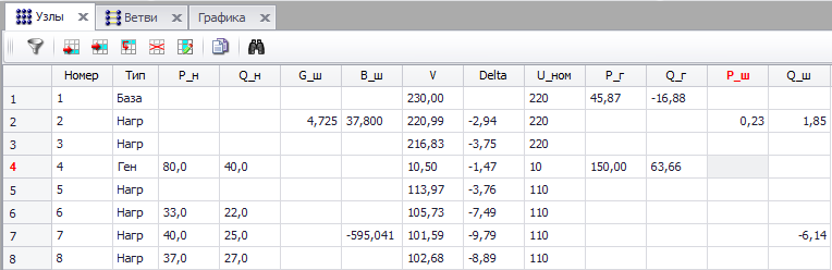
The result should be the following tables Nodes and Generators:
Branches
Let's move on to defining branches. There are two types of branches: a line and a transformer. The type of branch is determined by the value of the transformation coefficient: if Kt = 1 is a line; if Kt ≠ 1 is a transformer. To add the first branch, go to the Branches tab and add a line. Branches connect nodes, so you need to set a start and end node for all branches.
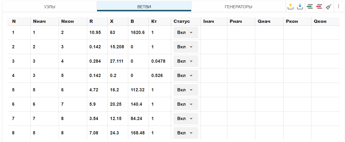
Branch 1-2 is an overhead line, for it it is necessary to set the resistance and conductivity.
Branch 2-3 is one of the AT branches that does not contain a transformer, so it is set similarly to overhead lines, without taking into account capacitive conductivity.
Branch 3-4 is the transformer branch, you need to set the transformation coefficient.
Branch 3-5 is a transformer branch with zero inductive resistance, for correct calculation it is necessary to set an inductive resistance of 0.2 ohms.
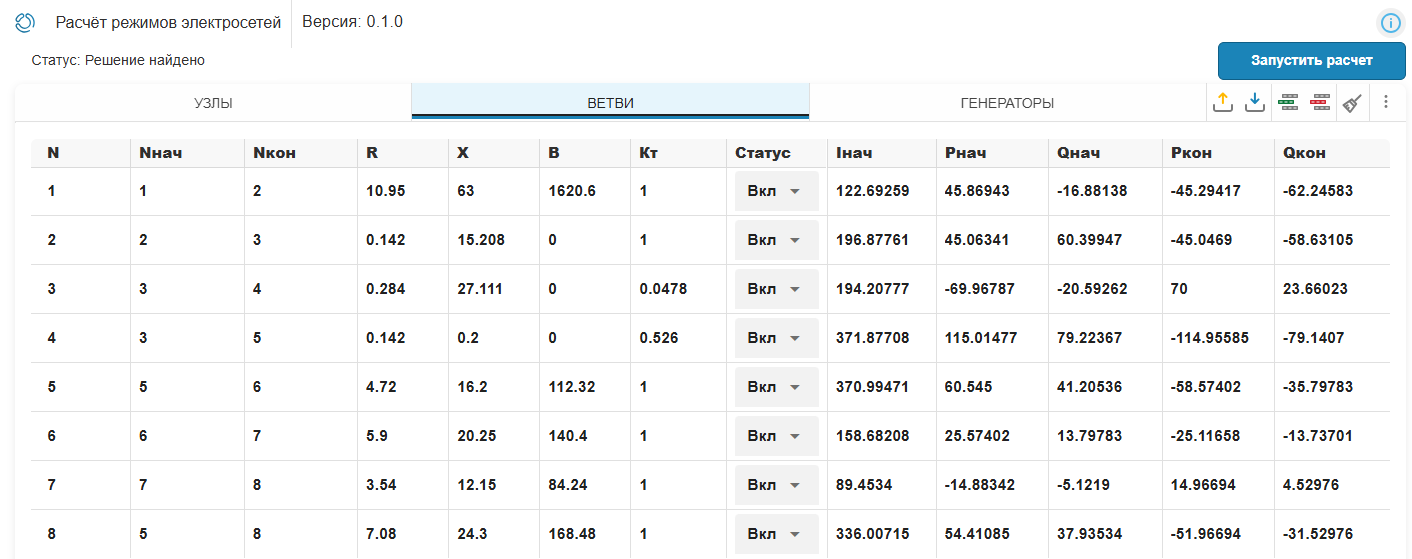
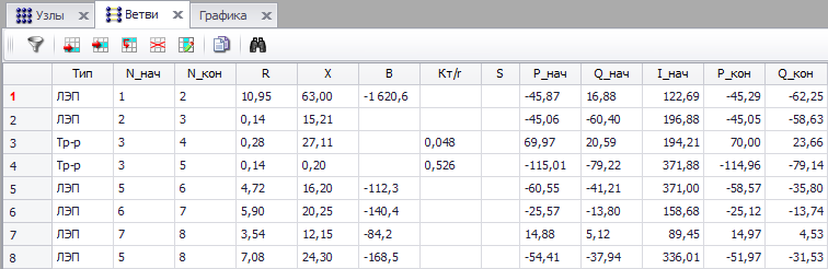
The other branches are overhead lines, set by analogy with branch 1-2. The result should be a branch table like this:
This completes the data entry stage.
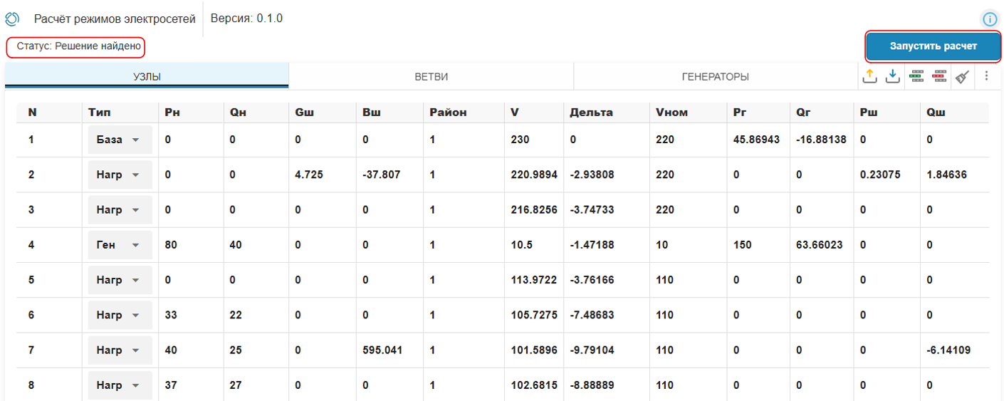
4. Calculation of the mode
To calculate the mode, press the Start calculation button. If everything is set correctly, the inscription Solution found will appear in the upper-left corner, and the calculated values of voltages and capacities will appear in the tables.
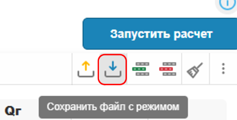
The calculation results can be saved using the Save file with mode button.
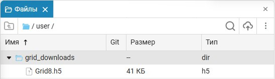
A directory with the saved mode file will appear in the Engee file browser.:
To verify that the data is set correctly and the mode is calculated, let's compare the results with the RastrWin program. The results of calculating the mode in RastrWin:
Note that in the application, the positive power direction is set from the bus to the line, and in RastrWin— from the end to the beginning. As a result, the branch capacity signs may vary.
Conclusions
This example showed how to calculate the parameters of the elements of the power system and calculate the steady-state mode using the application Calculation of power grid modes. The results obtained confirm the correctness of the application and its compliance with the calculations performed in the RastrWin program.