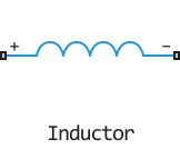
Inductor
Inductance coil.
blockType: AcausalFoundation.Electrical.Elements.Inductor
|
Path in the library: |
Description
The Inductor block models a linear inductance coil described by the following equation:
Where:
-
- voltage;
-
- inductance;
-
- current;
-
- time.
The Series resistance and Parallel conductance parameters represent small parasitic effects. Series resistance can be used to represent the ohmic resistance of a winding or the resistance caused by the skin effect. Some circuit modelling may require a small parallel conductance.
The + and - ports correspond to the positive and negative leads of the inductance coil, respectively. Current is positive if it flows from positive to negative and the voltage across the coil is equal to the potential difference across the positive and negative leads .
Ports
+ - positive
electricity
Electrical port, represents the positive terminal of the coil.
- is the negative
electricity
Electrical port, represents the positive terminal of the coil.
Parameters
Inductance - inductance of the coil
1e-6 Gn (by default) | positive | scalar
Coil inductance value.
Series resistance - series resistance
0 (by default) | non-negative | scalar
Parasitic series resistance. Series resistance can be used to represent ohmic winding resistance or resistance caused by the skin effect.
Parallel conductance - parallel conductance
1e-9 1/ohm (by default) | non-negative | scalar.
Parasitic parallel conductance. Modelling some circuits may require a small parallel conductance.
Initial value of current i - initial value of block current i
0 (By default)
Initial value of block current . Total current through the coil and parallel conductance.
Initial value of voltage v - initial value of voltage v
0 (By default)
Initial value of voltage .
Initial value of inductor current iL - initial value of coil current iL
`0 (By default)
Initial value of coil current . Coil current without taking into account parallel conduction.
