Operational Amplifier
The perfect operational amplifier.
blockType: AcausalFoundation.Electrical.Elements.OperationalAmplifier
|
Path in the library: |

Description
Block Operational Amplifier simulates an ideal operational amplifier. The figure shows the implementation scheme.
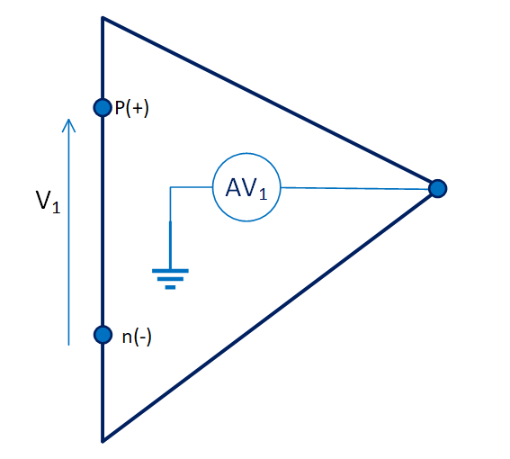
The block implementation is based on the following assumptions:
-
The gain of an ideal operational amplifier is considered infinite.
-
then for the final output it should be .
-
An ideal operational amplifier also implies that the current from + to − is zero. .
These assumptions lead to the following equations for the block:
Variables
Use the parameter group Initial Targets to set the priority and initial target values for the block parameter variables before modeling. For more information, see Configuring physical blocks using target values.
Ports
Conserving
#
+
—
non-inverting input
electricity
Details
The electrical port, which is the non-inverting input + of the operational amplifier.
| Program usage name |
|
#
−
—
inverting input
electricity
Details
The electrical port, which is the inverting input − of the operational amplifier.
| Program usage name |
|
#
out
—
exit
electricity
Details
The electrical port that represents the output of the operational amplifier.
| Program usage name |
|