Non-inverting operational amplifier
Introduction
This example shows the operation of a non-inverting operational amplifier.
Description of the model
The resistances are determined in the circuit of a non-inverting operational amplifier . Hence, the gain factor is defined as .
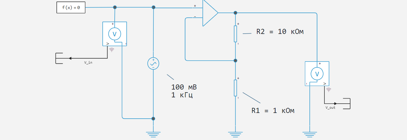
Since the operational amplifier unit implements an ideal device (i.e., with an infinite gain), a certain gain does not depend on the output load. Thus, at the amplitude of the input voltage at the output, it increases to an amplitude of .
Simulation results
As a result of the simulation, the input and output voltage graphs will have the form shown in the figure below.
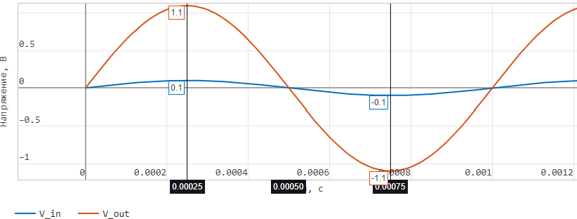
As can be seen from the graphs, the instantaneous voltage at the output of the operational amplifier is amplified 11 times.
Conclusion
In the considered example, a circuit of an ideal non-inverting operational amplifier is assembled and modeled.