Modeling of the lever system
In this example, we implement a lever transmission using physical modeling blocks.
Lever systems
Many mechanisms have levers in their composition: bicycle brakes and floor scales, piano hammers, a mechanism for lifting the body of a dump truck or a car trunk, hydraulic platforms and lever gears in the brakes of wagons.
They are often assembled into lever systems, or lever gears, and which may contain several levers, brackets, rods, suspensions, hinges, and other mechanical elements.
In this example, a model of such a device will allow us to find out what displacement or output force is produced by a lever system consisting of levers of the first, second and third kind.
Description of the model
In this example, we show how the block works. Lever (lever). Four levers are involved in the process:
- The first one (
Lever 1) and the fourth (Lever 4) are levers of the second kind, their fulcrum is located at one of the ends of the lever crossbar. The force is applied to the other end of the crossbar, and the load is placed in the middle - The third lever (
Level 3) is a lever of the first kind, its fulcrum is located in the center, between the force and the load - The second lever (
Lever 2) summarizes the work of all the others.
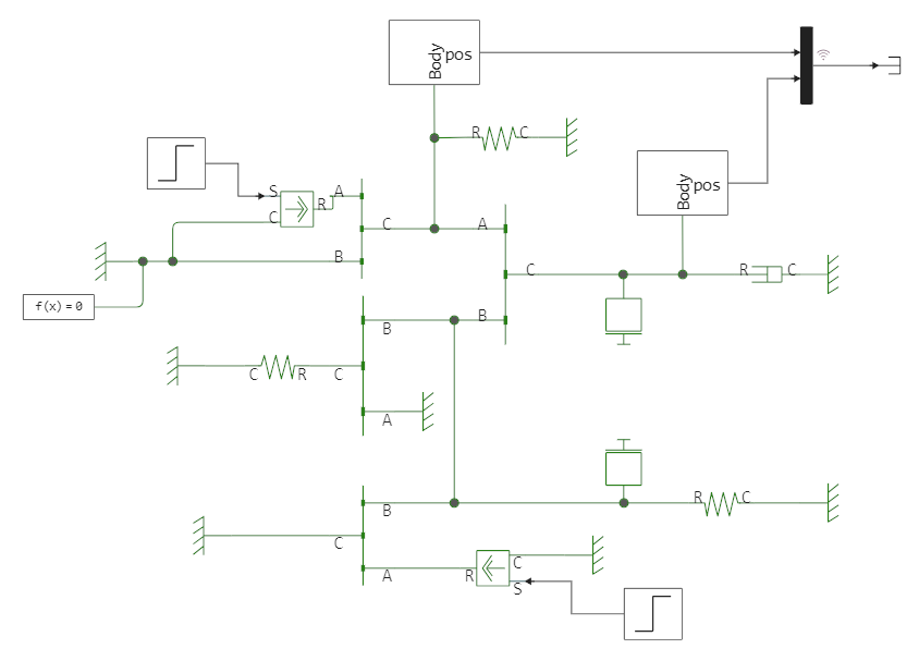
The above diagram shows a speculative mechanism. In addition to the levers, it contains dampers, springs and two blocks of mass. Since we are only looking at a model of the dynamics and kinematics of some part of the modeled mechanism, the blocks Mass They can be ordinary masses placed directly on the levers, or they can simulate an aerodynamic load. The same applies to sources of force – these can be models of the effect that the pilot exerts on the control pedals along the course of the aircraft, as well as models of any other interaction.
The described mechanism is influenced by two forces that begin to act at different points in time. At t = 1 s, a force of 100 N is applied to the free end of the lever Lever 1. Then, at t =2 s, a force of 200 N is applied to the end of the lever bar Lever 3.
Launching the model
Let's run the model using the [program control] commands (https://engee.com/helpcenter/stable/modeling/programmatic-modeling.html ).
modelName = "linkage_mechanism"
model = modelName in [m.name for m in engee.get_all_models()] ? engee.open( modelName ) : engee.load( "$(@__DIR__)/$modelName.engee" );
model_data = engee.run( modelName )
plot( model_data["out"].time, hcat(model_data["out"].value...)' )
As we expected, we see the effect of two unifying influences.
Conclusion
The Engee physical modeling blocks allow you to model various mechanisms, and due to the graphical nature of these models, the user can spend less time composing equations, and more time on system analysis, requirements compilation, and model environment development for our development.