Checking the static behavior of the thyristor when it is turned on
In this example, we will check that the behavior of the switched-on thyristor in steady state corresponds to the parameters specified in the settings of its unit.:
V_GT = 0.6;     # In
I_GT = 3e-6;    # But
V_T = 1.2;      # In
I_T = 1.0;      # But
Rs = 87.0;      # cOm
Test 1. Checking the release voltage
In the Thyristor_Static_Behavior_On_1.engee model, the thyristor starts when a pulse of 3 µA or more is applied to the gate (Gate trigger current, I_GT).
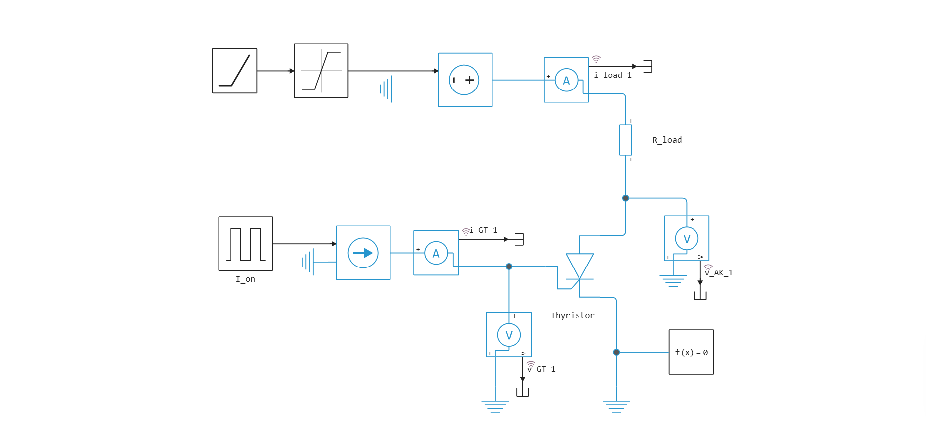
Test conditions:
- Supply voltage . The supply voltage should not be applied abruptly, but gradually, using the Linear Signal block (Ramp), in order to prevent dv/dt starting.;
- Load
- There is no external gate resistor in the circuit, therefore, to turn on the device with a 3 µA pulse, it is necessary to set the value of the internal shunt resistance (Rs) . If the resistance is low, the thyristor will not operate at the input current. , and if, on the contrary, it is too high, then the thyristor will work at a current lower than .
V_s1 = 12;         # In
R_load1 = 120;    # Om
I_on1 = I_GT;      # A
In this test, we will check that the unlocking voltage on the control electrode is equal to the Corresponding gate voltage, V_GT, 0.6 V, specified in the settings, when the current in the control electrode is equal to the switching current of the thyristor, Gate trigger current, I_GT, 3 Ma.
Launching the model
engee.addpath(@__DIR__)
if "Thyristor_Static_Behavior_On_1" in [m.name for m in engee.get_all_models()]
    m = engee.open( "Thyristor_Static_Behavior_On_1" ) # loading the model
else
    m = engee.load( "Thyristor_Static_Behavior_On_1.engee" )
end
results_1 = engee.run(m, verbose=true)
Getting parameters
t_1 = results_1["i_GT_1"].time;         # Time
i_GT_1 = results_1["i_GT_1"].value;     # Gate current
v_GT_1 = results_1["v_GT_1"].value;     # Voltage between gate and cathode
i_load_1 = results_1["i_load_1"].value; # Load current
v_AK_1 = results_1["v_AK_1"].value;     # Forward voltage
Plotting graphs
using Plots
plotlyjs();
plot(layout=@layout([a a; b b;]), legend=:outerbottomright)
plot!(t_1, i_GT_1, subplot=1, ylabel="Current, A", w = 2, linecolor =:blue, label="Gate current")
plot!(t_1, v_AK_1, subplot=2, ylabel="Voltage, V", w = 2, linecolor =:orange, label="Forward voltage")
plot!(t_1, i_load_1, subplot=3, xlabel="Time, c", ylabel="Current, A", w = 2, linecolor =:green, label="Load current")
plot!(t_1, v_GT_1, subplot=4, xlabel="Time, c", ylabel="Voltage, V", w = 2, linecolor =:red, label="Voltage between gate and cathode")
The graphs show that the thyristor starts when a 3 µA pulse is applied to the gate, and the voltage between the gate and the cathode is really close to 0.6 V.
Test 2. Checking the voltage drop of an open thyristor
The Thyristor_Static_Behavior_On_2.engee model uses a thyristor with the same settings. In this test, we will check that the voltage drop of the open thyristor , corresponds to the parameters specified in the thyristor settings (On-state voltage) when the load current is on (On-state current) .
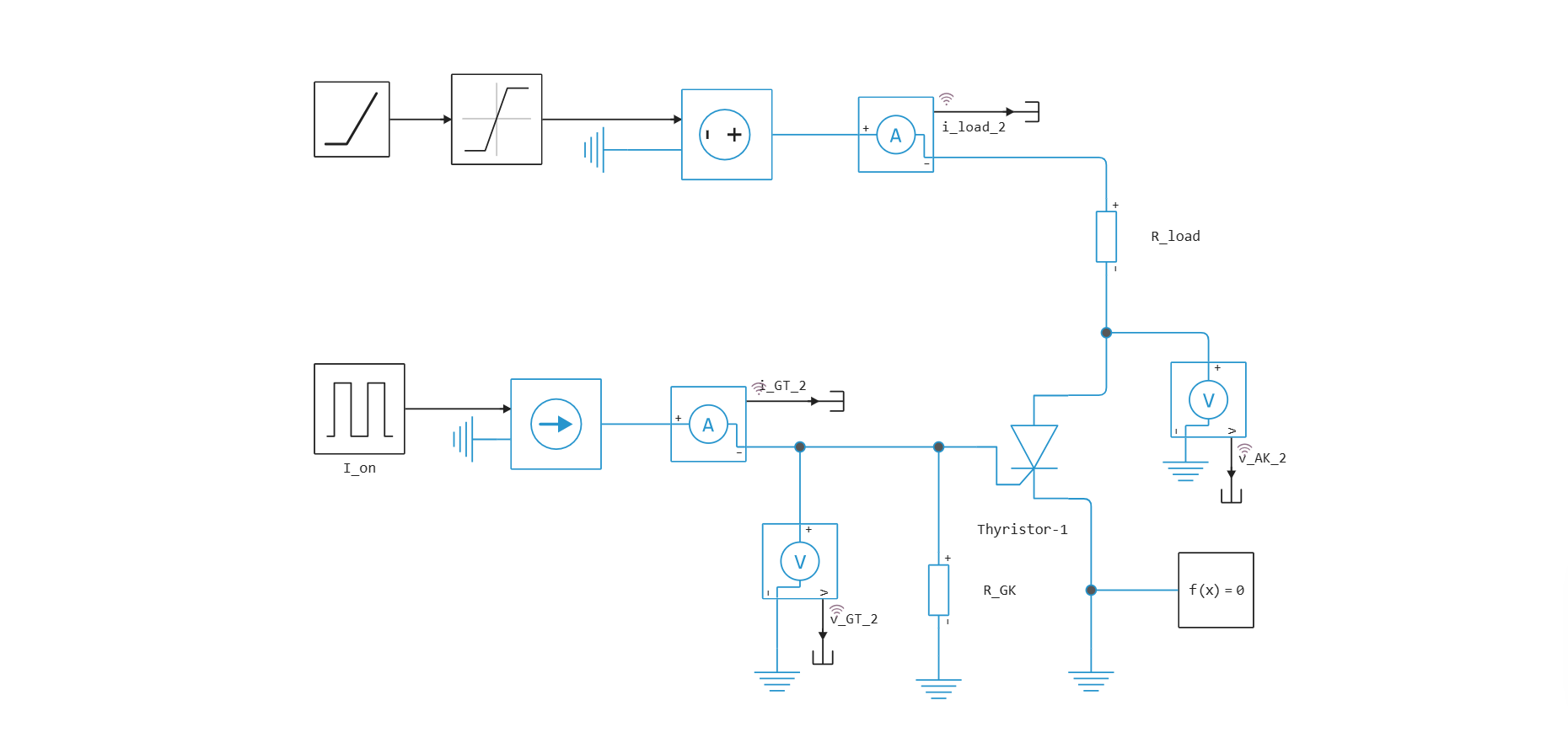
Test conditions:
- Supply voltage (gradual feeding);
- Load ;
- External resistor reduces the sensitivity of the thyristor operation. The trip current increases to approximately . The critical current will be slightly less due to the increased current, the anode is a gate, which contributes to the gate current.
V_s2 = 12;          # In
R_load2 = 10.8;     # Om
R_GK = 1000;        # Om
I_on2 = 0.6*1e-3;   # But
Launching the model
if "Thyristor_Static_Behavior_On_2" in [m.name for m in engee.get_all_models()]
    m = engee.open( "Thyristor_Static_Behavior_On_2" ) # loading the model
else
    m = engee.load( "Thyristor_Static_Behavior_On_2.engee" )
end
results_2 = engee.run(m, verbose=true)
Getting parameters
t_2 = results_2["i_GT_2"].time;         # Time
i_GT_2 = results_2["i_GT_2"].value;     # Gate current
v_GT_2 = results_2["v_GT_2"].value;     # Voltage between gate and cathode
i_load_2 = results_2["i_load_2"].value; # Load current
v_AK_2 = results_2["v_AK_2"].value;     # Forward voltage
Plotting graphs
using Plots
plotlyjs();
plot(layout=@layout([a a; b b;]), legend=:outerbottomright)
plot!(t_2, i_GT_2, subplot=1, ylabel="Current, A", w = 2, linecolor =:blue, label="Gate current")
plot!(t_2, v_AK_2, subplot=2, ylabel="Voltage, V", w = 2, linecolor =:orange, label="Forward voltage")
plot!(t_2, i_load_2, subplot=3, xlabel="Time, c", ylabel="Current, A", w = 2, linecolor =:green, label="Load current")
plot!(t_2, v_GT_2, subplot=4, xlabel="Time, c", ylabel="Voltage, V", w = 2, linecolor =:red, label="Voltage between gate and cathode")
The graphs show that the load current in the switched-on state is 1 A and at this current the voltage drop between the anode and the cathode is really close to 1.2 V.
Conclusion
After conducting two tests to turn on the thyristor, we made sure that the static behavior of the thyristor corresponds to the parameters specified in the settings of its unit.