Semi-bridge converter
A half—bridge converter is a type of DC-DC converter that uses two semiconductor switches (usually MOSFET or IGBT transistors) connected in series between a DC source. The principle of its operation is based on alternating switching of these switches to create an alternating voltage, which is then converted to a constant output.
Advantages of semi-bridge converters
- Simple design with two keys, choke and capacitor. This reduces the number of components and the size of the printed circuit board.
- The ability to operate with a wide input voltage range of 85-265 V without the need for multiple secondary windings.
- Higher efficiency compared to other topologies due to reduced conduction and switching losses.
- The ability to provide electrical isolation between the input and output stages for safety-critical applications.
- The possibility of step-up and step-down power conversion using a single transformer stage.
- Smaller dimensions and higher specific power compared to bridge converters.
Modeling in Engee
Let's look at the model of this device in Engee:
Simulation of the power unit
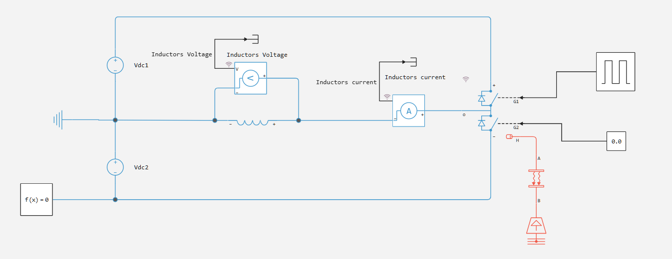
We will simulate our converter using the Half-Bridge (Ideal, Switching) block. Unlike classical circuits, instead of capacitors, we will take two sources of constant voltage (in the Vdc model).
We will control the opening and closing of transistors using the Pulse Generator. To demonstrate, we will control only one key, and always keep the other one private. Like any electronics, our converter is heated, and the thermal port H is used to account for the dissipated heat. It is worth noting that the block allows you to take into account the thermal effects separately for each of the keys.
Accounting for thermal phenomena
Since our converter is heating up, it may be interesting for us to simulate the effect of the heat generated and the temperature of the device. For this, the Half-Bridge (Ideal, Switching) unit has a thermal port H. You can split the thermal port H into two separate thermal ports connected to the upper and lower switching devices, respectively, by selecting the "Separate thermal ports for upper and lower devices" option. If you separate the thermal ports for the upper and lower devices, you can also separate the thermal ports for the integrated diodes of each switching device by selecting the option "Separate thermal ports for integral diodes". The upper and lower switching devices have the same thermal parameters.
Simulation and results
Open the model and run the simulation.:
demoroot = @__DIR__
mdl = engee.open(joinpath(demoroot,"m6_half_bridge_simple.engee"))
result = engee.run(mdl);
let's look at the currents and voltage on the load:
using Plots

Ic = collect(result["Inductors current"]);
Vc = collect(result["Inductors Voltage"]);

p = plot(Ic.time,Ic.value, label = false, title = "Load current", layout = (1,2))
p = plot!(Vc.time,Vc.value, label = false, title = "Load voltage", subplot = 2)
Conclusion
In this project, the semi-bridge converter and its advantages were considered. Next, this device was modeled in Engee.