Measuring the angle of a stepper motor using a Hall effect encoder
This example shows how to determine the angle of rotation of a stepper motor using a Hall effect encoder unit.
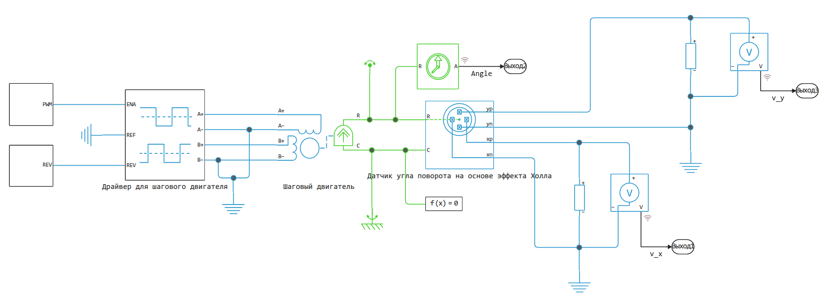
The Encoder unit simulates an angular position sensor using four Hall sensors evenly positioned under a rotating magnet. Each Hall sensor outputs an output voltage proportional to the magnetic field strength. The sensors are located along the poles of the rotating magnet and have a maximum magnetic flux density at different positions of the magnet orthogonal to the main axes of measurement. Thus, the sensors generate four sinusoidal signals shifted by 90° relative to each other. These four signals uniquely encode the rotation of the sensor shaft over the entire 360° range.
This example shows two models. In both cases, the stepper motor rotates first up from 0° to 360°, and then down from 360° to 0°:
-
In the model
HallEffectRotaryEncoderVoltageThe encoder is configured so that its output ports output electrical signals. They output the voltage at the output of each Hall sensor. -
In
HallEffectRotaryEncoderAngleThe encoder unit is configured to output the measured angle at once.
Model Overview
Let's open the first model.
cd(@__DIR__) # Go to the folder with the example
engee.open("HallEffectRotaryEncoderVoltage.engee");
Let's run the model and study the results.:
data = engee.run("HallEffectRotaryEncoderVoltage")
plot(
    plot( data["v_x"].time, [data["v_y"].value data["v_x"].value], lw=2, title="Sensor output voltage and measured angle", titlefont=font(11), guidesfont=font(8), ylabel="Voltage(V)", label=["V_y" "V_x"] ),
    plot( data["Angle"].time, 180/pi*data["Angle"].value, lw=2, xlabel="Time (s)", ylabel="Angle (degrees)", label=false, guidesfont=font(8)),
    layout=(2,1), size=(900,500)
)
When the motor rotates in different directions, we see how the voltages on the sensors of the X and Y axes change along the sine wave. When the poles of the magnet coincide with the axes of the sensors, we see the maximum values of this signal. At the beginning of the simulation, the magnetic poles align with the sensors xnand xp. This coincidence creates a maximum output voltage at ports xn and xp (Vx) and zero voltage at ports yn and yp (Vy). When the shaft starts rotating, Vx decreases and Vy increases as the north pole moves towards yp, and the southern one is to yn.
Simplified model
Open the model HallEffectRotaryEncoderAngle.
engee.open("HallEffectRotaryEncoderAngle.engee");
.png)
Let's run the model and discuss the results.:
data = engee.run("HallEffectRotaryEncoderAngle")
plot( data["Angle"].time, 180/pi*data["Angle"].value,
lw=2, xlabel="Time (s)", ylabel="Angle (degrees)", label=false, guidesfont=font(8), size=(900,400) )
The results of the models are quite comparable.
In the second configuration, the negative angle is subtracted from 360, so we get a visible jump around zero. In the first model, negative angles are displayed without correction.
Conclusion
Using several simple components, it was possible to create a model of a step motor and a system for measuring its rotations, which can be included in a semi-natural simulation cycle and controlled by a virtual model from a real microcontroller.