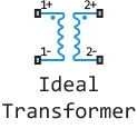
Ideal Transformer
The perfect transformer.
blockType: AcausalFoundation.Electrical.Elements.IdealTransformer
|
Path in the library: |
Description
Block Ideal Transformer It is an ideal transformer described by the following equations:
Where:
-
— primary voltage;
-
— secondary voltage;
-
— the current of the primary winding;
-
— secondary winding current;
-
— transformation coefficient.
This unit can be used to represent either an alternating current transformer or a semiconductor DC-to-DC converter. To simulate a transformer taking into account inductance and mutual inductance, use the block Mutual Inductor.
Each of the two electrical networks connected to the primary and secondary windings must have its own unit Electrical Reference.
Ports
The unit has four electrical ports. The polarity is indicated by the signs ** and *−* . The ports marked 1 and 1− are connected to the primary winding. The ports marked 2+ and 2− are connected to the secondary winding.
Parameters
Winding ratio — pass transformation coefficient:q[<br>] 1 (by default) | scalar | positive
The transformation coefficient, or the ratio of the number of turns of the primary winding to the number of turns of the secondary winding.
Initial value of primary current i1 — initial value of primary current i1
0 (by default)
The initial value of the primary winding current .
Initial value of primary voltage v1 — initial value of primary voltage v1
0 (by default)
The initial value of the primary winding voltage .
Initial value of secondary current i2 — initial value of secondary current i2
0 (by default)
The initial value of the secondary winding current .
Initial value of secondary voltage v2 — initial value of secondary voltage v2
0 (by default)
The initial value of the secondary winding voltage .
