Semi-natural simulation on KPM RHYTHM (Conveyor control on ARIES PLK200)
This example continues the development of the pipeline modeling project. We are fully moving on to semi-natural modeling: we transfer the control algorithm from the Chart Engee block to CODESYS V3.5, connect the ARIES PLK200 programmable logic controller to the RHYTHM semi-natural modeling complex, and run the physics and cargo model on the tape in real time. This
way we will be able to test the embedded control logic without a control object - on the Engee model in real time, testing all possible scenarios of the program, exploring it and upgrading it taking into account the behavior of the object without significant costs.
Introduction
In the previous example of the project, we implemented pipeline automation in Engee and tested it in real time. After minor improvements to the real-time execution of the model, we will proceed to full-fledged [semi-natural testing] (https://engee.com/helpcenter/stable/en/ritm.html ):
-
instead of the controller simulation unit in the model, the signals will be transmitted to DI/DO KPM RHYTHM,
-
to DI/DO KPM RHYTHM will connect, having agreed, the I/O programmable logic controller ARIES PLK200,
-
program the PLC by implementing the control algorithm described in the Chart block.
The example model
The control system model of the current example looks as shown in the figure below.:
Here, instead of the PLC model, as it was in the previous example, we use two peripheral units [GP-LC-45 general purpose module] (https://engee.com/helpcenter/stable/en/ritmex-gp-lc-45/blocks.html ) KPM RHYTHM:
-
GP-LC-4x DI "Digital inputs" - for transmitting digital signals to KPM RHYTHM and the Engee model from PLC,
-
GP-LC-4x DO "Digital outputs" - for transmitting digital signals from the Engee and KPM RHYTHM models to the PLC.
GP-LC-45 Module Blocks
The DI block forms, by analogy with the [Chart] block(https://engee.com/helpcenter/stable/en/state-machines/chart.html ) from the previous example, three output signals:
-
Engine on/off,
-
Cargo placement signal,
-
the signal of the removal of the arrived cargo.
In the GP-LC-4x DI block, respectively, we define the following parameters:
-
Module number: 1,
-
Number of channels: 3,
-
Resistor lift for power supply: no,
-
Calculation step, from: 1e-3 (model calculation step).
On the DO block as well, by analogy with the [Chart] block(https://engee.com/helpcenter/stable/en/state-machines/chart.html ) from the previous example, one logical input signal is transmitted:
- The load can be removed.
This signal must be scaled to the module voltage level (5 V) and the data type converted to Float64.
In addition, one signal of a constant level of 5 V is transmitted to the unit to supply voltage to the relay modules of the PLC inputs/outputs and the matching circuit.
In the GP-LC-4x DO block, respectively, we define the following parameters:
-
Module number: 1,
-
Number of channels: 2,
-
Calculation step, from: 1e-3 (model calculation step).
Connecting ARIES PLK200 to KPM RHYTHM
The PLC model used is ARIES [PLK200-01-CS](https://owen.ru/product/plk200 ?ysclid=mf6u0519lb23774853). This controller has 8 fast digital inputs (FDI1-FDI8) and 14 digital relay outputs (DO1A, DO1B - DO14A, DO14B). Accordingly, signals with a voltage level of +24 V (PLC power level) must be transmitted to the controller, and at the controller input, contacts A and B of the digital outputs will close the circuits transmitting control actions to the KPM RHYTHM.
Connect the PLC to the RHYTHM inputs as follows:
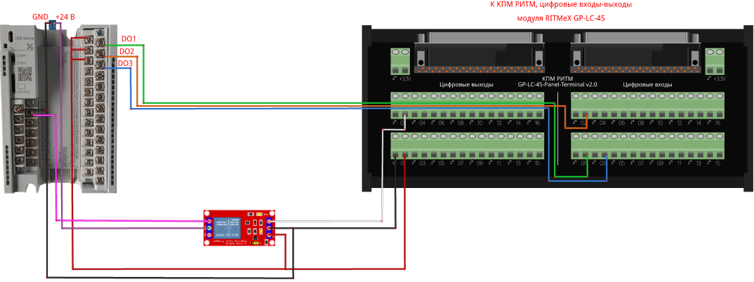
The contacts DO1A-DO3A of the PLC receive a voltage of +5V from the output DO1 terminal of the GP-LC module. PLC control signals are sent from contacts DO1B-DO3B to the inputs DI01-DI03 of the terminal of the GP-LC module.
The output of the DO2 terminal of the module is connected to the signal input IN of the external relay module. It also receives +5V power from the terminal.
The relay contacts of the relay module COM and NO (normally open contact) are connected, respectively, to the 24 V power supply and the fast input FDI1 of the PLC. The SS1 (common) pin is also connected to the common contact of the power supply.
After connecting the PLC, you can proceed to its configuration and programming.
PLC control logic
Let's transfer the logic described in the chart block of the previous example to a PLC program written in languages according to IEC 61131-3. The development environment is CODESYS version 3.5_SP17_Patch3.
The control logic of the model is implemented in the form of a state diagram, as shown below:
.png)
After the transfer in the LAD language to CODESYS, the control logic takes the following form:
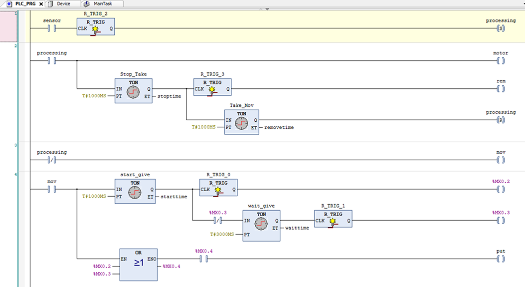
The names of the variables are preserved here, and temporal transitions between states are expressed as TON timers. The two upper circuits correspond to the process of removing the load that has arrived at the ultrasonic sensor. The lower two chains correspond to the process of feeding loads to the belt.
This control logic can also be represented in FBD language.:
.png)
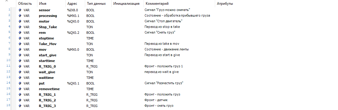
To correlate variable names and hardware inputs/outputs, consider the variable declaration area of the CODESYS diagram.:
.png)
So, PLC outputs DO1, DO2, DO3 are connected to memory addresses %QX0.0, %QX0.1, %QX0.2 accordingly.
PLC input FDI1 - with address %IX8.0.
Marker addresses are used as follows:
%MX0.0- activation (by holding) of the statemov(Diagram chain No. 4),%MX0.1- activation (in the SET function) of the stateprocessing(Diagram chain No. 2),%MX0.2- transmission of the signal front to deliver the load to the belt after starting the engine,%MX0.3- cyclic transmission of the signal edge to deliver the load to the belt,%MX0.4- transmission of signal edges from markers%MX0.2and%MX0.3.
After debugging the program and programming the controller, we proceed to semi-natural modeling.:
HIL-testing of PLC control logic
Before conducting HIL-тестирование the following steps have been completed with the PLC:
-
upgraded the model,
-
DI/DO PLCs are connected to DI/DO KPM RHYTHM,
-
the program for the PLC has been moved from the model,
-
the PLC program is debugged, the PLC is programmed,
-
the program is running on the PLC.
Now it remains to carry out, if necessary, preparation for work with KPM RHYTHM and run the Engee model interactively:
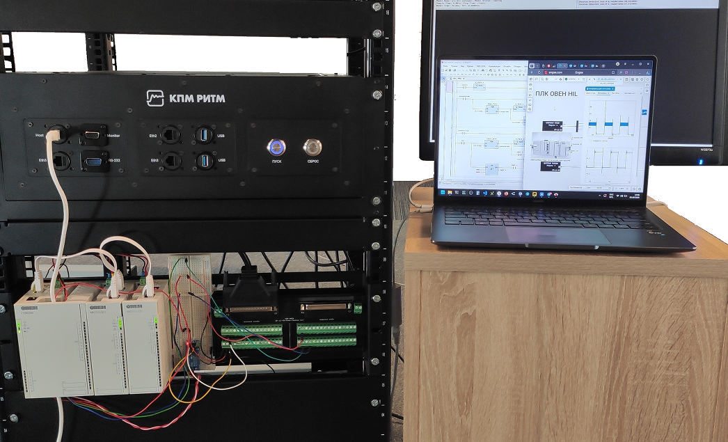
The model running on the KPM RHYTHM in real time exchanges discrete signals with the PLC, as defined in the control logic and at the simulation stage in Engee. The control system accurately implements the inherent logic.
Next, you can proceed to scaling the control system in the model and on the PLC, testing various operating conditions of the control facility, analyzing the operation of the control system, as well as integrating other devices and interfaces for comprehensive semi-natural testing.
Conclusion
In this example, we looked at a semi-natural simulation in hard real time for a pipeline with a control system implemented on a PLK200 programmable logic controller from ARIES. The control logic was previously developed in the Chart block of the model and tested in Engee. At this step, it has been transferred to Codesys without changes.