Semi-natural simulation on KPM RHYTHM (DPT current regulator on STM32)
One of the real-time testing scenarios implemented at KPM RHYTHM in Engee is semi-natural simulation. With its help, we can, for example, simulate a real physical object by exchanging signals with its control system running on a microcontroller. This example shows how to transfer the controller to the controller and perform a full-fledged semi-natural simulation. The control object here is the DC motor current circuit on the KPM RHYTHM, and the control system is the PI current regulator on the STM32F446RE microcontroller.
Introduction
A complete reference list of the tools and approaches used in this example:
-
Model-oriented design environment Engee
-
The app РИТМ.Управление машинами
-
Integration внешнего оборудования in Engee
-
Маски кодовых ячеек scripts
-
-
The complex of semi-natural RHYTHM modeling (КПМ РИТМ)
-
Real-time test scenario - полунатурное моделирование (HIL)
-
General purpose module RITMeX GP-LC-45: 2 channels ЦАП, 1 channel АЦП with terminal GP-LC-45-Terminal v1.0
-
-
Automatic генерация С-кода from the Engee model
-
Nucleo debugging board with STM32F446RE microcontroller
- 2 ADC channels, 1 PWM channel
-
IDE VS Code
-
-
STM32F4 support package
-
The framework stm32duino
-
-
Hardware-In-the-Loop (HIL)
Semi-natural simulation technology, or Hardware-In-the-Loop (HIL), is based on replacing individual subsystems with their real-time models. These models exchange data with other subsystems via the same interfaces that real subsystems use. The controllers or units operate in the same mode as usual, and the engineer has ample opportunities for development and testing [[1]](https://habr.com/ru/companies/etmc_exponenta/articles/848778 /).
In this example, we will consider a semi-natural simulation of an automatic current control system (current loop) of a DC motor with independent excitation. The model of the physical object will be modeled on the KPM RHYTHM in real time. We will generate the current regulator from the model into code and load it onto the STM32F446RE microcontroller. By connecting the analog inputs and outputs of the microcontroller and the semi-natural simulation complex, we will perform semi-natural simulation in real time.
The ultimate goal of such a scenario is to transfer part of the model (controller) to a real physical object (microcontroller), and using HIL to achieve identical results in simulation and semi-natural simulations.
The example model
The model of the current example is a functional continuation of the model discussed in the example real-time testing automation времени. The differences from the original model are as follows:
- In callbacks, the reference voltage of the control system takes the value (instead of
- The source of the signals of a given current is a block of a rectangular pulse generator (instead of a block of a step function) with a period , the percentage of filling and the amplitude
- A circuit with interface blocks [GP-LC-4x] has been added in parallel to the current regulator (https://engee.com/helpcenter/stable/ru-en/ritmex-gp-lc-45/blocks.html ) DAC and ADC for receiving and transmitting data via analog inputs and outputs with a microcontroller.
- Blocks have been added to offset, limit, and extract the signal when working with interface blocks.
- Before modeling, the control signal source for the control object model can be switched using a manual switch unit.
The GP-LC-4x module is configured as follows:
-
DAC: module: , channels: , the calculation step: ;
-
ADC: module: , channels: , voltage level: , mode: with common ground, calculation step: .
The displacement levels should be calibrated before the start of the semi-normal tests. Saturation levels at the input of the DAC unit are set according to the maximum input voltage levels of the microcontroller's ADC: .
Connecting to KPM RHYTHM
To minimize manual operations during semi-natural modeling, we will use the external hardware support package in Engee.
Let's install this package.
engee.package.install("Engee-Device-Manager");
You can find out how to configure the connection in the client program and work with the methods of the support package in the example of automation of real-time testing времени.
At this stage, you also need to connect the RHYTHM, establish a connection with it from Engee, and update its operating system and support package, if necessary. How to do this is presented in detail and step by step in the example quick start with KPM RHYTHM.
After the preparation, we will establish a connection with KPM RHYTHM:
# @markdown ## Connecting KPM RHYTHM

IP = "192.168.56.3" # @param {type:"string",placeholder:"192.168.56.3"}
порт = "8000" # @param {type:"string",placeholder:"8000"}

using Main.EngeeDeviceManager.Targets
using Main.EngeeDeviceManager.Targets.RITM_API

ritm = Targets.RITM.Ritm()
Targets.RITM_API.setUrl(ritm, "http://$IP:$port/")

println("KPM RHYTHM is connected: ", RITM_API.isConnected(ritm))
Now let's move directly to modeling. To begin with, let's repeat the experience of real-time simulation from the original example.
Real-time simulation on KPM RHYTHM
Let's run the example model on KPM RHYTHM:
# @markdown ## Running the model in Standalone mode
имя_модели = "hil_dcm" # @param {type:"string",placeholder:"hil_dcm"}
path = joinpath(@__DIR__, "$model name.engee")
model = engee.load(path)
resp = Targets.upload_model(ritm, model)
println("\n", "Loading the model: ", resp)
resp = Targets.generate_executable_code(ritm, model, false)
println("\n", "Code generation: ", resp)
resp = Targets.compile_model(ritm, model)
println("\n", "Compilation: ", resp)
Targets.start_model(ritm, model)
engee.close(model; force=true)
The real-time simulation was successful, and the KPM RHYTHM monitor displays the preset signal and graphs of the armature current and EMF of the converter. We'll get a screenshot of the monitor:
RITM_API.getScreenshot(ritm, "model.png")
The regulator is set to the modular optimum, and the corresponding overshoot and delay of the transient process are observed on the current graph. Now let's move on to semi-natural modeling.
Preparing for HIL
First of all, we will transfer part of the current regulator model to physics: we will generate the code from the PI controller subsystem and upload it to the microcontroller.
Code generation
# Generating the code from the subsystem:
engee.generate_code(joinpath(@__DIR__, "$имя_модели.engee"), joinpath(@__DIR__, "cg_res"); subsystem_name="PI_reg")

# Transfer the generated files to the folders of the PlatformIO project
for file in readdir("cg_res")
    if file == "main.c" # the template main.c is not portable, as there is already a ready-made main.cpp
        nothing
    elseif last(file)=='h'
        mv(joinpath(@__DIR__, "cg_res", file), joinpath(@__DIR__, "PlatformIO_proj/include", file); force=true)
    else
        mv(joinpath(@__DIR__, "cg_res", file), joinpath(@__DIR__, "PlatformIO_proj/src", file); force=true)
    end
end

# Let's remove the excess
rm(joinpath(@__DIR__, "cg_res"); recursive=true)
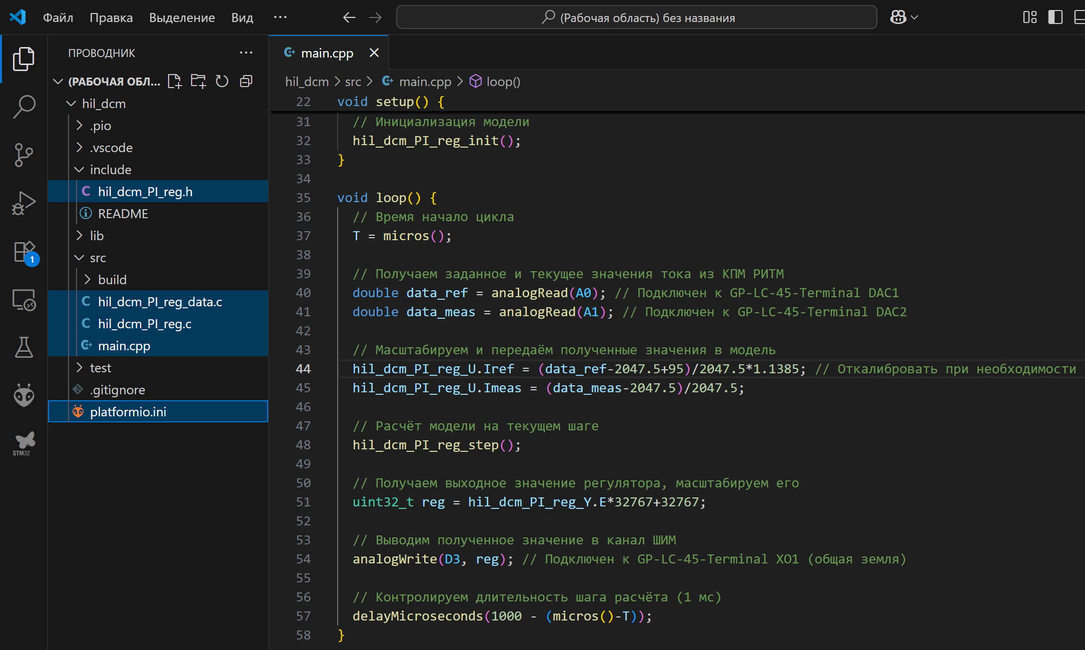
Received in the folder PlatformIO_proj the files are required to build the project in VS Code PlatformIO. Download them and add them to the project in an external IDE.
Example project in VS Code PlatformIO
The added files in the PlatformIO project look like this:
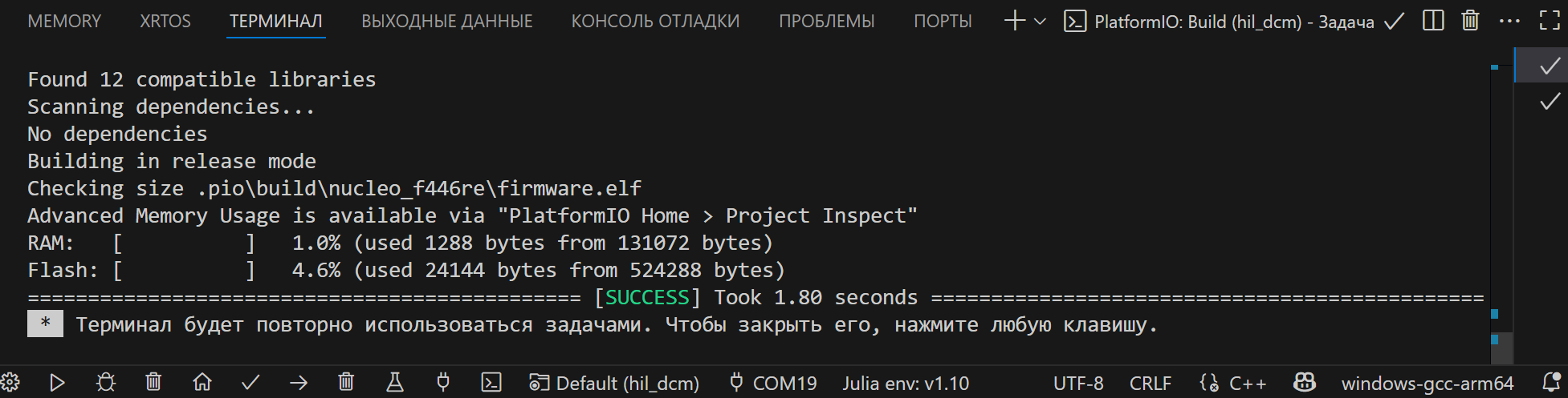
Before building the project, you need to make sure that the necessary support packages for PlatformIO are installed, after which you can proceed to building the project.:
Transferring the code to the MCU
Let's start building the project:
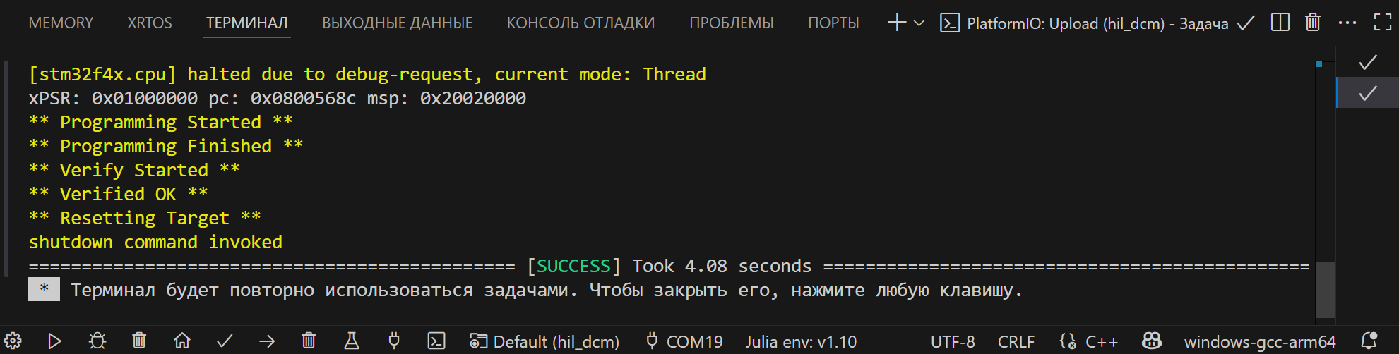
The project assembly is successful, and you can proceed to uploading the code to the microcontroller. Connect the controller and load the compiled code into it.:
.png)
After uploading the generated code to the microcontroller, we will connect the analog inputs/outputs of KPM RHYTHM and NUCLEO-F446RE.
Connecting to the MCU
Before connecting, the voltage from the devices must be removed, in addition, the effects of static electricity on the chips should be avoided. Install the connections as shown in the diagram.
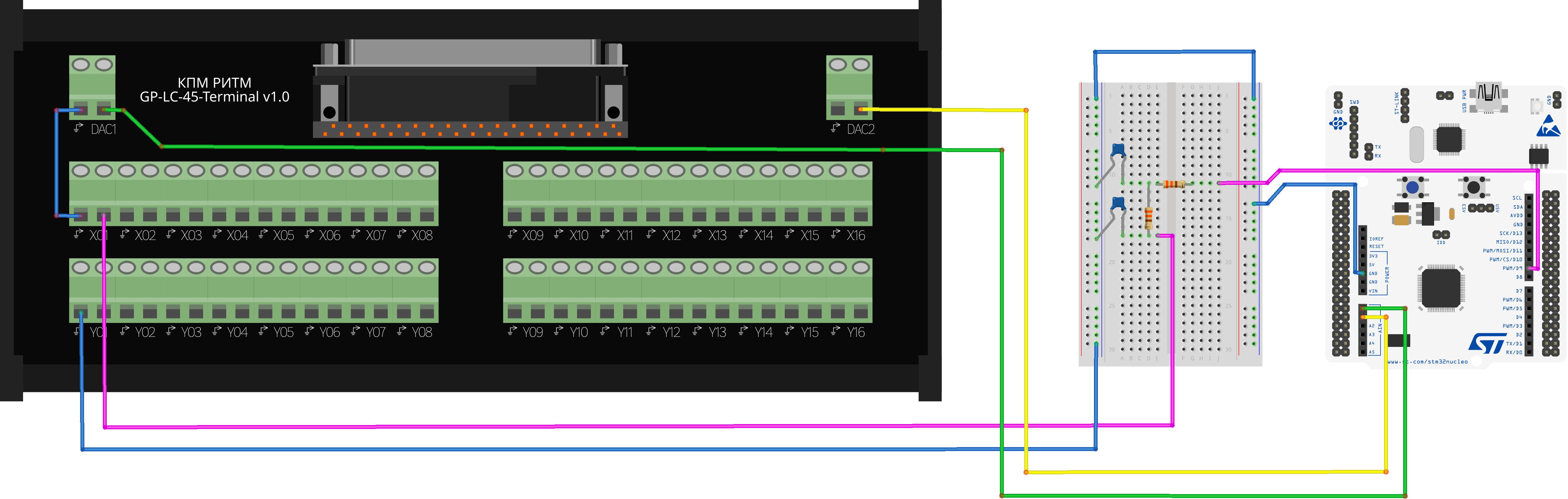
We will connect the common contacts of the analog outputs and analog inputs of the terminal, the common contacts of the breadboard and the microcontroller.
Analog terminal inputs DAC1, DAC2 connected to the analog inputs of the microcontroller A0, A1 accordingly.
Analog output of the microcontroller D9 connected to the analog input of the terminal X01 through a cascaded RC low-pass filter. Cutoff frequency , chain parameters: , .
Part of the simulated system has been transferred to the STM microcontroller, after all the power supply connections to the circuit, you can switch to semi-natural modeling.
Semi-natural simulation of the DPT current circuit
First of all, we will edit our model: we will switch the manual switch, so that the control object in the model will receive control signals from the microcontroller:
# Loading the model
имя_модели = "hil_dcm"
path = joinpath(@__DIR__, "$model name.engee")
model = engee.load(path)
# Changing the switch position
engee.set_param!("$имя_модели/Ручной переключатель", "PortValue" => true)
# Saving changes
engee.save(model, path; force = true)
# Closing the model
engee.close(model)
Now let's upload the modified model to the RHYTHM and execute it.:
# @markdown ## Running the model in Standalone mode
имя_модели = "hil_dcm" # @param {type:"string",placeholder:"hil_dcm"}
model = engee.load(joinpath(@__DIR__, "$имя_модели.engee"))
resp = Targets.upload_model(ritm, model)
println("\n", "Loading the model: ", resp)
resp = Targets.generate_executable_code(ritm, model, false)
println("\n", "Code generation: ", resp)
resp = Targets.compile_model(ritm, model)
println("\n", "Compilation: ", resp)
Targets.start_model(ritm, model)
engee.close(model; force=true)
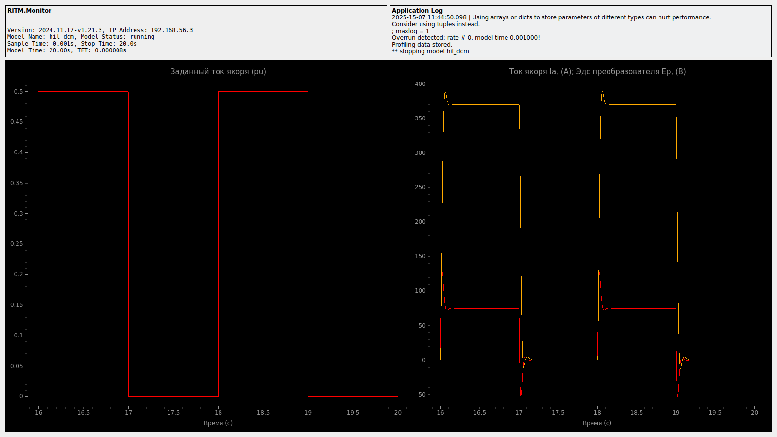
The semi-natural simulation was successful, and the KPM RHYTHM monitor also shows the preset signal and graphs of the armature current and EMF of the converter. We'll get a screenshot of the monitor:
RITM_API.getScreenshot(ritm, "model.png")
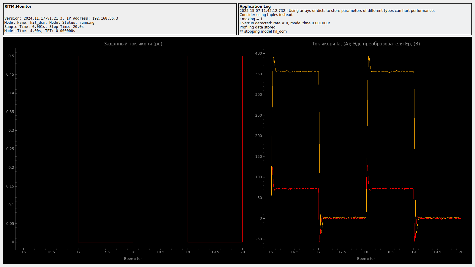
As can be seen from the current graph, there is more overshoot in this simulation mode, and the established value is lower. Dynamic and static errors of the ATS indicate inefficient adjustment of the regulator, which is the result of the model's lack of consideration of delays and distortions introduced by the electronic circuit for transmitting analog signals between the MCU and the rhythm. For the further development of the project, it is necessary to take these elements into account in the Engee model.
Conclusion
In this example, we examined the process of transferring part of the controller model of the automatic control system to a digital microcontroller by generating code from the Engee model, step-by-step disassembled the process of preparing and conducting a semi-natural modeling experiment, and also used automation of work with external equipment for effective modeling in Engee on the RHYTHM.
Additional sources
- [How to build a semi-natural stand with KPM RHYTHM](https://habr.com/ru/companies/etmc_exponenta/articles/848778 /)