Discrete-Time Integrator
Discrete integration or accumulation of a signal.
blockType: DiscreteIntegrator
|
Path in the library: |

Description
Use the block Discrete-Time Integrator instead of a block Integrator to create a completely discrete model.
Output equations
At the first time step, i.e. at the state of the block , output value .
For a given step over the simulation time output data they are updated depending on the selected method as follows:
-
The direct Euler method:
.
-
The inverse Euler method:
.
-
The trapezoid method:
.
The implementation of these output equations in the state space is automatically selected depending on the block calculation step, which can be explicit or inherited. When using an explicitly specified calculation step reduced to the calculation step for everyone .
Methods of integration and accumulation
This unit can integrate or accumulate a signal using the forward Euler method, the inverse Euler method, or the trapezoid method. Suppose that — this is the entrance, — this is the way out, eh "It’s a condition. For a given step updated and . In the integration mode — this is the block calculation step. In accumulation mode . The block calculation step determines when the output signal is calculated, but not the output value. — gain factor. The values are trimmed according to the upper or lower limit.
The direct Euler method
The direct Euler method (used by default), also known as the straight rectangular or left approximation.
The block approximates how . Expressions for the block output in the step :
,
.
The block uses these steps to calculate the output signal.:
Step 0: |
(limited if necessary)
|
Step 1: |
|
Step n: |
(limited if necessary) |
The inverse Euler method
The inverse Euler method, also known as the inverse rectangular or right-handed approximation.
The block approximates how . Expressions for the block output in the step :
,
.
The block uses these steps to calculate the output signal.:
Step 0: |
(limited if necessary)
|
Step 1: |
|
Step n: |
|
Determination of initial states
You can define the initial states as a parameter in the dialog box of the block or enter them from an external signal.:
-
To define the initial states as a block parameter, specify Initial condition source how
internaland enter the value in the field Initial condition. -
To get the initial states from an external source, specify Initial condition source how
external. An additional input port appears under the input port.

When to use the status port
Use the status port instead of the output port in the following cases:
-
When the block output returns to the block through the reset port or the initial state port, causing an algebraic loop.
-
When it is required to transfer state from one conditionally executed subsystem to another, which can cause synchronization problems.
You can work around these issues by passing the state through the status port rather than the output port. Engee generates the state at a slightly different time than at the output, which protects the model from such problems. To display the block status, check the box Show state port. The status port will appear at the top of the block.

Limitation of the integrator
To ensure that the output data does not exceed the specified levels, check the box Limit output and enter the restrictions in the appropriate parameter fields. This action results in the block functioning as a limited integrator. When the output reaches the limit values, the integrator operation ends.
The block defines the output data as follows:
-
When the integral is less than or equal to Lower saturation limit, the output signal is held at Lower saturation limit.
-
When the integral is between Lower saturation limit and Upper saturation limit, the output is an integral.
-
When the integral is greater than or equal to Upper saturation limit, the output signal is held at Upper saturation limit.
To generate a signal indicating when the state is limited, check the box Show saturation port. The saturation port appears under the block output port.

The signal takes one of three values:
-
1indicates that the upper limit is applied. -
'0` indicates that the integral is not limited.
-
The
-1indicates that the lower limit is applied.
Reset the status
The block resets its state to the initial state on an external signal. The type of reset trigger is determined by the parameter External reset. When selecting a value other than none the unit has a reset port, next to which the type of reset trigger is indicated.

Types of reset triggers
Parameter External reset allows you to define the reset signal attribute that is the reset trigger. The following triggers are possible:
-
rising— resets the state when the reset signal passes the edge, i.e. increases from a negative or zero value to a positive one. For example, the figure below shows the effect of a reset trigger.risingfor integration by the inverse Euler method.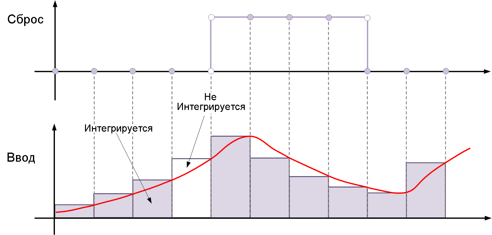
-
falling— resets the state when the reset signal is cut off, i.e. it drops from a positive value to zero or a negative value. For example, the figure below shows the effect of a reset trigger.fallingfor integration by the inverse Euler method.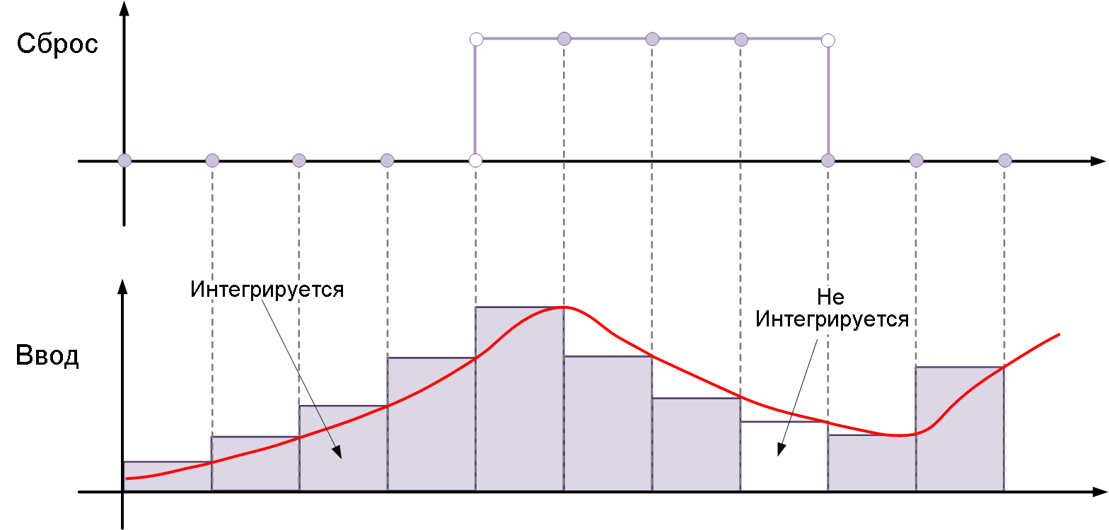
-
either— resets the state when the reset signal rises or falls, i.e. it changes from zero to a non-zero value, from a non-zero value to zero, or changes sign. For example, the following figure shows the effect of a reset triggereitherfor integration by the inverse Euler method.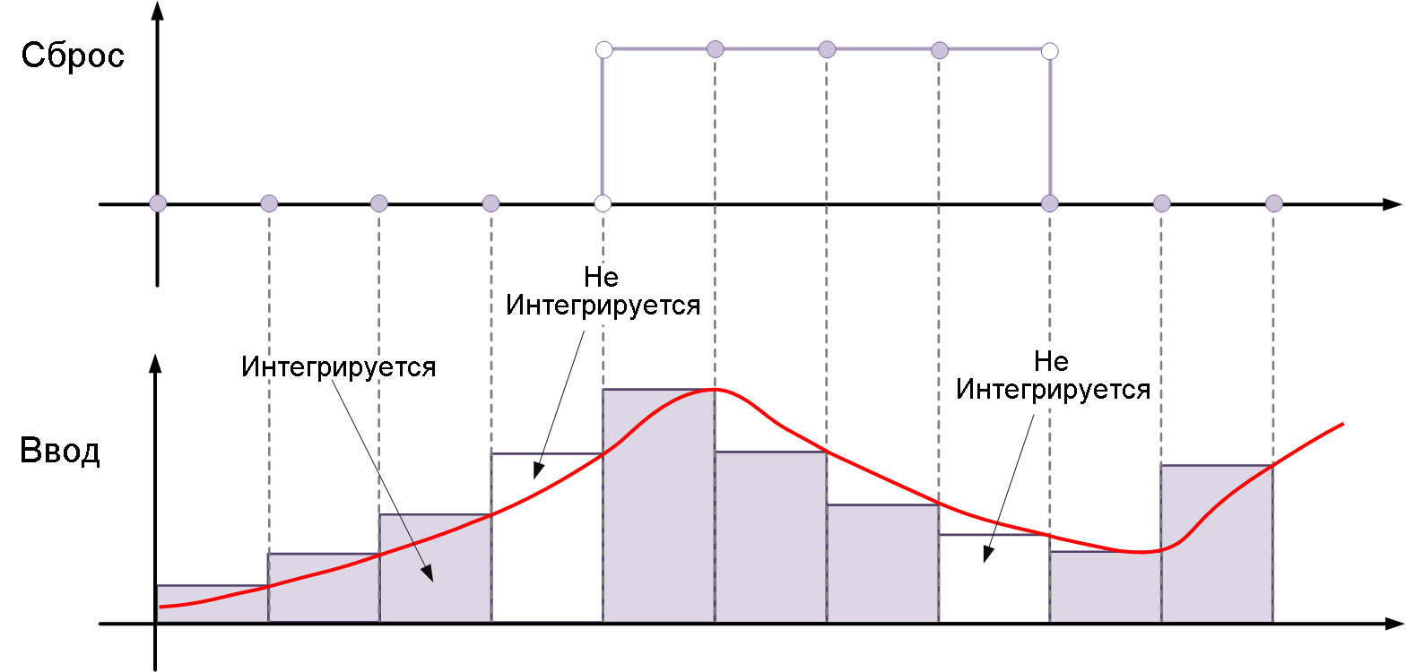
-
level— resets and holds the output in its initial state until the reset signal is zero, i.e. it is different from zero at the current time step or changes from a non-zero value at the previous time step to zero at the current time step. For example, this picture shows the effect of a reset trigger.levelfor integration by the inverse Euler method.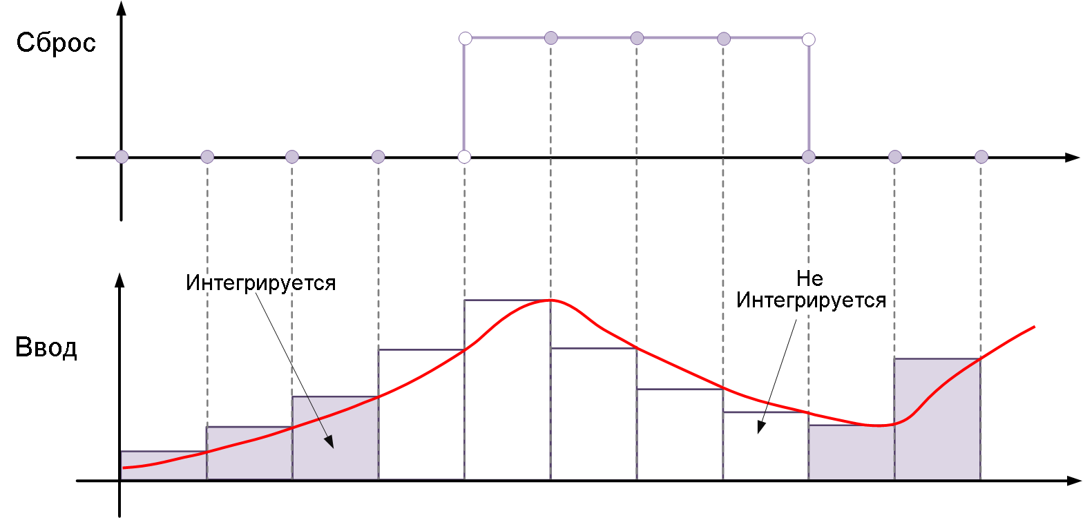
-
sampled level— Resets the output signal to its initial state when the reset signal is non-zero. For example, this picture shows the effect of a reset trigger.sampled levelfor integration by the inverse Euler method.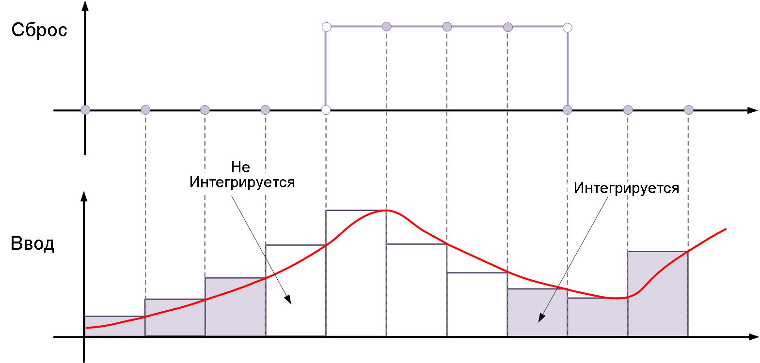
Option sampled level it requires less calculations, which makes it more efficient than the option level.
For the block Discrete-Time Integrator all triggers are detected by signals with positive values. For example, a signal varying from -1 to 0 is not considered a rising edge, but a signal varying from 0 to `1' is.
|
Ports
Output
#
Port_1
—
the discrete-time integral or the accumulated value of the input signal
scalar | vector | the matrix
Details
The discrete-time integral or the accumulated value of the input signal.
| Data types |
|
| Complex numbers support |
No |
Input
#
Port_1
—
The input signal
scalar | vector | the matrix
Details
An input signal specified as a scalar, vector, or matrix.
The signal can only be of the type Float32 and Float64.
| Data types |
|
| Complex numbers support |
No |
Parameters
Main
#
Integrator Method —
The integration method
Integration: Forward Euler | Integration: Backward Euler | Integration: Trapezoidal | Accumulation: Forward Euler | Accumulation: Backward Euler | Accumulation: Trapezoidal
Details
The method of integration or accumulation.
| Values |
|
| Default value |
|
| Program usage name |
|
| Tunable |
No |
| Evaluatable |
No |
#
Gain Value —
integrator gain factor
Scalar / array of real numbers
Details
Specifies the scalar, vector, or matrix by which the integrator’s input signal is multiplied. Each element of the gain factor must be a positive real number.
-
Specifying a value other than
1.0(default value), semantically equivalent to connecting a block Gain to the integrator’s entrance.
| Acceptable values |
|
Using this parameter to specify the input gain eliminates the multiplication operation in the generated code. However, this parameter must be non-configurable in order to realize this advantage. If you want to change the gain, set this parameter to 1.0 and use an external unit Gain to set the gain factor.
|
| Default value |
|
| Program usage name |
|
| Tunable |
No |
| Evaluatable |
Yes |
#
External reset —
reset the status to the initial one
none | rising | falling | either | level | sampled level
Details
Specify the type of trigger to be used for the external reset signal.
-
rising— resets the state when the reset signal passes the edge. -
falling— resets the state when the reset signal is cut off. -
either— resets the state when the reset signal rises or falls (passes the edge or slice). -
level— Resets and holds the output in its initial state until the reset signal is zero. -
sampled level— Resets the output signal to its original state when the reset signal is non-zero.
For more information, see the sections Reset status and Types of reset triggers.
| Values |
|
| Default value |
|
| Program usage name |
|
| Tunable |
No |
| Evaluatable |
No |
#
Initial condition source —
selecting the source of the initial state
internal | external
Details
The source of the initial state. Set as:
-
internal— getting the initial states from the parameter Initial condition. -
external— receiving initial states from an external source via the input port x0.
Dependencies
Choice internal enables the use of the parameter Initial condition in the simulation.
Choice external disables the use of the parameter Initial condition and it turns on the input port x0.
| Values |
|
| Default value |
|
| Program usage name |
|
| Tunable |
No |
| Evaluatable |
No |
#
Initial condition —
initial state
Scalar / array of real numbers
Details
The initial state of the block.
Dependencies
To use this parameter, set for the parameter Initial condition source meaning internal.
| Default value |
|
| Program usage name |
|
| Tunable |
Yes |
| Evaluatable |
Yes |
#
Initial condition setting —
selecting the application of the initial state
Auto | Output
Details
Select whether to apply the parameter value. Initial condition to the state of the block or to the output of the block. The initial state is also the reset value.
-
Auto— the block applies the value of the parameter Initial condition to the entrance of the block.Set the initial states:
x(0) = ICWhen resetting:
x(n) = IC -
Output— the block applies the value of the parameter Initial condition to the exit of the block.Set the initial states:
y(0) = ICWhen resetting:
y(n) = IC
| Values |
|
| Default value |
|
| Program usage name |
|
| Tunable |
No |
| Evaluatable |
No |
#
Sample time —
the interval between the calculation steps
SampleTime (real number / vector of two real numbers)
Details
Specify the interval between the calculation steps as a non-negative number. To inherit the calculation step, set this parameter to −1.
Do not specify a calculation step equal to 0. This value sets the continuous calculation step, which is the block Discrete-Time Integrator It doesn’t support it. Do not specify the calculation step inf or NaN because these values are not discrete. If you specify −1 to inherit a calculation step from a higher-level block, make sure that the higher-level block uses a discrete calculation step. For example, the block Discrete-Time Integrator cannot inherit a calculation step equal to 0.
|
| Default value |
|
| Program usage name |
|
| Tunable |
No |
| Evaluatable |
Yes |
#
Limit output —
limiting the output values of the block to the specified range
Logical
Details
Limits the output signal to parameter values Lower saturation limit and Upper saturation limit.
-
If this option is selected, the output signal is limited to the parameter values. Lower saturation limit and Upper saturation limit.
-
Unchecking this option removes the limitations on the output signal.
Dependencies
Selecting this option involves using the parameters Lower saturation limit and Upper saturation limit.
| Default value |
|
| Program usage name |
|
| Tunable |
No |
| Evaluatable |
No |
#
Show saturation port —
enabling the saturation output port
Logical
Details
Select this option to add the saturation output port to the block. When you uncheck this box, the unit does not have a saturation output port.
Dependencies
Selecting this parameter turns on the saturation output port.
| Default value |
|
| Program usage name |
|
| Tunable |
No |
| Evaluatable |
No |
#
Show state port —
enabling the status output port
Logical
Details
Select this option to add the status output port to the block. When you uncheck this box, the unit does not have a status output port.
Dependencies
Selecting this option turns on the status output port.
| Default value |
|
| Program usage name |
|
| Tunable |
No |
| Evaluatable |
No |