Rapid prototyping of control algorithms at KPM RHYTHM: three-phase inverter
This example shows how to use two KPM RHYTHM real-time machines in rapid prototyping control algorithms in the event that there is no real control object. The control object is a three-phase autonomous inverter model. The inverter is controlled by a PWM signal, which is generated by the current control system in DQ coordinates. The example contains four models:
-
converter_with_control_system.engee— a management object model with a management system that is debugged in Engee. -
converter_for_ritm_1.engee— a model of the control object to be launched at KPM RHYTHM No. 1. The control signals are received via the GP-ID-4x digital input module. Transfer of measurements via the GP-AD-24 module DAC. -
control_system_for_ritm_2.engee— control system model for launching at KPM RHYTHM No.2. Measurements are taken using the GP-LC-4x digital input module ADC. Transmission of the PWM signal through the digital outputs of the GP-LC-4x module. -
converter_with_discrete_control_system.engee— a model of a control object with a discrete control system from which a C code is generated.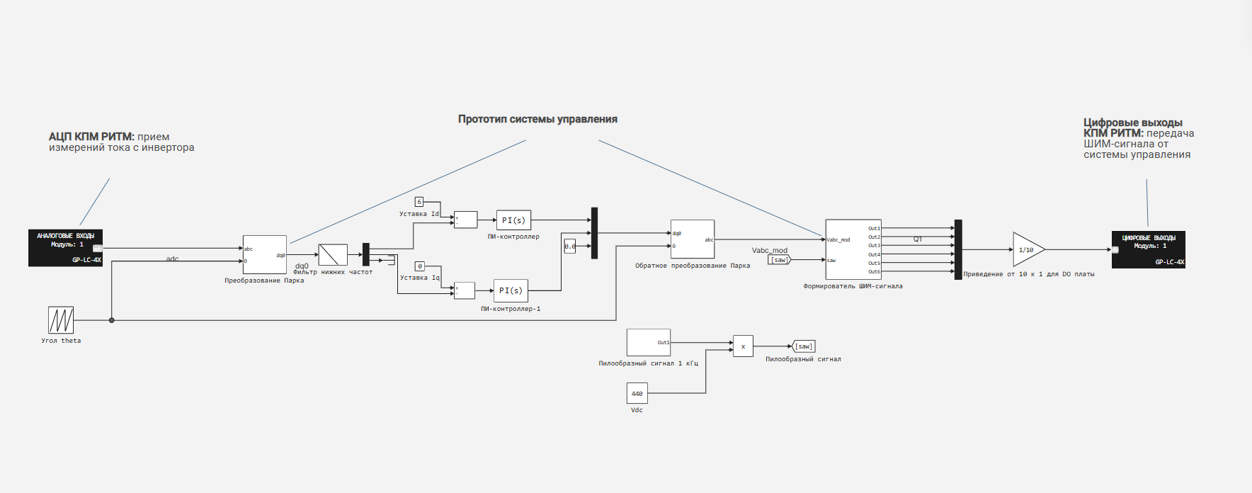
Introduction
Inverters play an important role in modern electric power systems, as they are the main link for integrating constant voltage sources (for example, solar panels and energy storage devices) into the grid. For their correct operation, it is necessary to develop control systems that meet the requirements of safety and reliability. This example demonstrates an effective and iterative method of developing control systems - rapid prototyping.
The traditional way, which is shown in example with a stepper motor (installing the prototype directly on a real object) in our case with a powerful three-phase inverter is practically inapplicable.
-
It is unsafe (risk of equipment damage due to control errors);
-
Roads (requires a ready-made power unit and a complete wiring diagram);
-
Inconvenient for debugging (difficult to isolate and reproduce scenarios).
Instead, it is proposed to consider an alternative approach, which is as follows:
Divide the system into two parts:
-
The control object (inverter and network) is modeled on one KPM RHYTHM;
-
The control system (PWM, DQ regulators and logic) works ** on another KPM RHYTHM** as a rapid prototype.
An inverter model with a control system
The original model converter_with_control_system.engee It contains a model of a three-phase autonomous inverter with a control system based on a PWM signal, which is generated by a current control system in DQ coordinates. The model is used for debugging outside of real time (simple launch in Engee):.png)
Principles of the inverter control system
When we control an inverter, our goal is to control the current it supplies to the load or network. But the current in a three—phase system is constantly changing - it is sinusoidal, and it is difficult to control it directly. To simplify the task, we use a mathematical "trick": we transfer three-phase currents from a rotating coordinate system (ABC) to a stationary DQ system.:
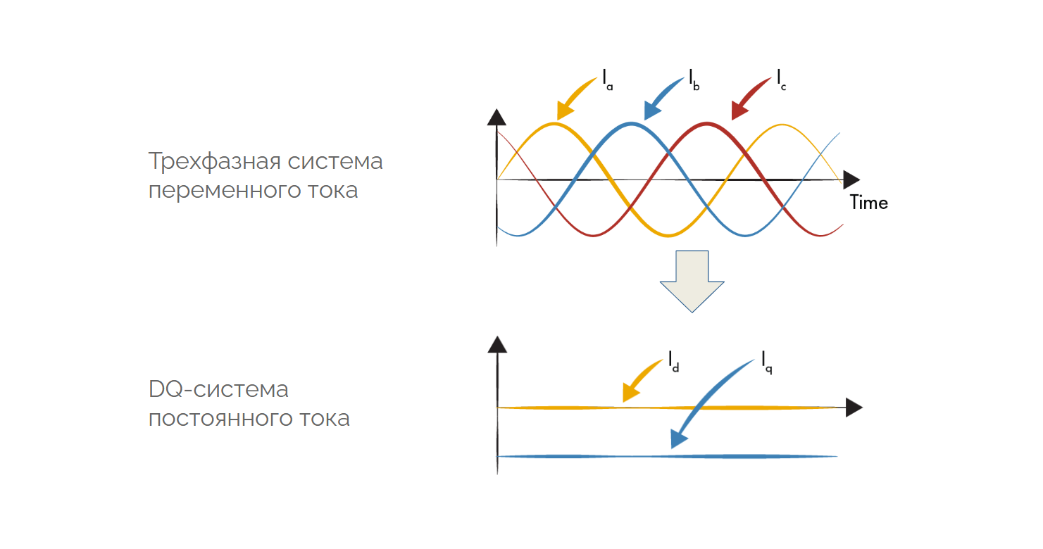
In this system, the currents can be easily compared with the setpoint and adjusted using a PI controller.
After we have "adjusted" the values in the DQ system, we return back to the rotating ABC and generate a PWM signal to control the six power switches in the three-phase inverter.:
.png)
Simulation results:
It can be seen that the values of Id and Iq eventually come to the settings set in the model.
Management object model for KPM RHYTHM No. 1
converter_for_ritm_1.engee — a model of the control object to be launched at KPM RHYTHM No. 1. The control signals are received via the GP-ID-4x digital input module. Transfer of measurements via the GP-AD-24 module DAC. The calculation step is 50 microseconds.
.png)
Management system model for KPM RHYTHM No. 2
control_system_for_ritm_2.engee — control system model for launching at KPM RHYTHM No.2. Measurements are taken using the GP-LC-4x ADC module. Transmission of the PWM signal through the digital outputs of the GP-LC-4x module. The calculation step is 50 microseconds.
.png)
Launching models on KPM RHYTHM
The stand consists of KPM RHYTHM "Mobile", KPM RHYTHM "Productive" and terminal blocks for connecting reception and transmission boards. Additionally, an oscilloscope is used to monitor the transmitted measurements.
.png)
Real-time model launch:
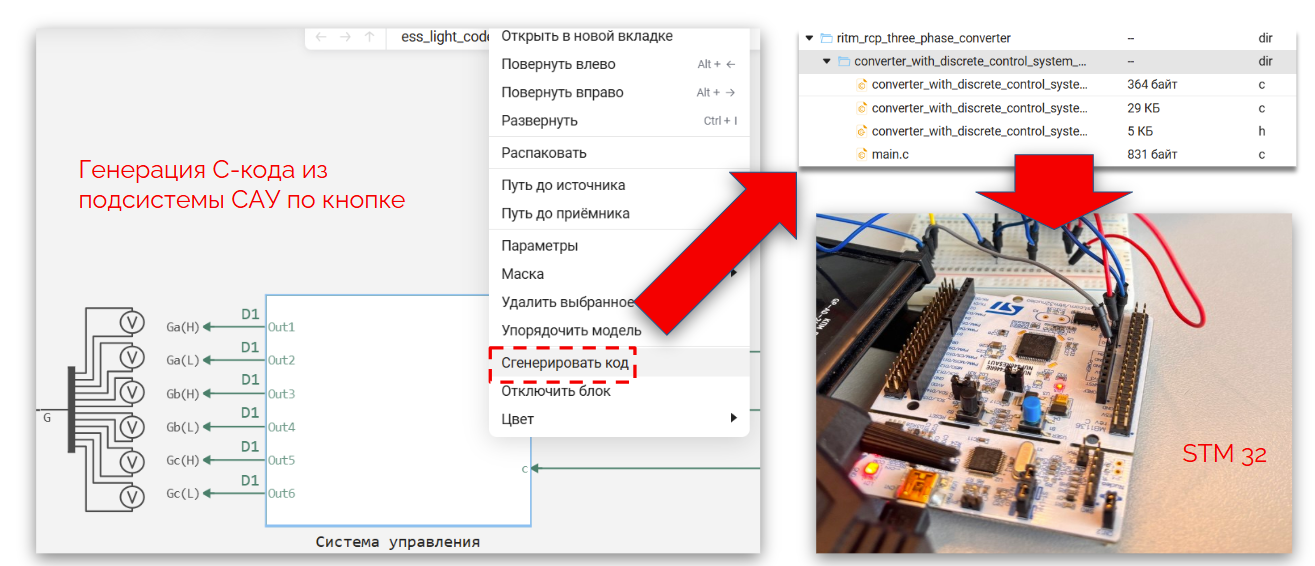
Generating a C code from a control system
A separate stage after debugging on real-time software and hardware complexes may be the generation of C code from the model for further deployment on the microcontroller. A separate section of the documentation is devoted to the generation of the C code, where it is indicated список blocks from which the code is automatically generated.
converter_with_discrete_control_system.engee — a model that is equivalent to the simulation results of the original model converter_with_control_system.engee, but at the same time, its control system has been completely reassembled, taking into account the features described above.
.png)
As you can see from the screenshot, the control system model is highlighted in green, which means it contains blocks operating at the same frequency D1.
Now we can right-click on the block and generate the C code for the subsystem, which can be used to flash the microcontroller (this example does not cover this process).
.png)
Conclusion
In the example, we used the approach of rapid prototyping of control algorithms using semi-natural RHYTHM modeling complexes and Engee automatic code generation tools. The initial model of the control system and facility was developed and debugged at Engee. Further, the model is divided into two parts: the model of the control object and the model of the control system. Each of the models is running on a separate KPM RHYTHM. After receiving positive debugging results in real time, a C code was generated from the control system model.