Converter (Three-Phase)
Controller-controlled bidirectional three-phase AC/DC converter.
blockType: AcausalElectricPowerSystems.Converters.ThreePhase
|
Path in the library: |

Description
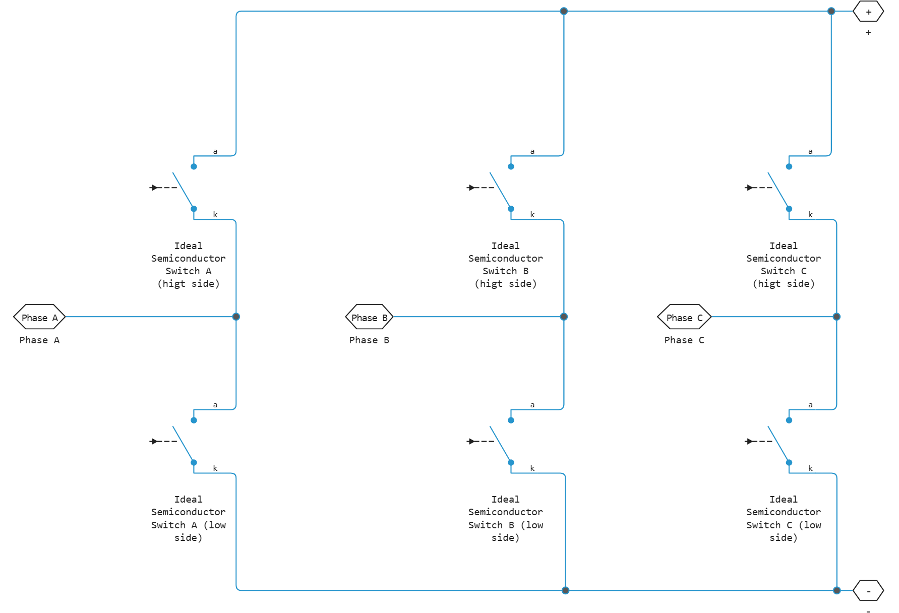
The unit Converter (Three-Phase) models a six-pulse three-phase controlled converter consisting of three bridge arms. Each bridge arm consists of two switching devices. The converter circuit connects a three-phase AC network to a DC network.
Each component in the three-arm circuit is the same switching device, which is defined in the parameters Switching device. The switching devices that can be defined are implementations of blocks from the library Semiconductors & Converters:
-
GTO- latched thyristor. For information on the volt-ampere characteristic of the device, see GTO. -
Ideal Semiconductor Switch- ideal solid-state controlled switch. For information on the volt-ampere characteristic of the device, refer to Ideal Semiconductor Switch. -
IGBT- Insulated gate bipolar transistor. For information on the volt-ampere characterisation of the device, see IGBT (Ideal, Switching). -
MOSFET- n-channel MOSFET for switching circuits. For information on the volt-ampere characteristic of the device, see MOSFET (Ideal, Switching). -
Thyristor- piecewise linear thyristor. For information on the volt-ampere characteristic of the device, see Thyristor (Piecewise Linear). -
Averaged Switch- A solid-state switch with an antiparallel diode. The control signal port G takes values in the interval[0, 1]. When G is0or1, the averaged switch is fully open or fully closed, respectively. The switch behaves similarly to the Ideal Semiconductor Switch block with an anti-parallel diode. When G is between0and1, the averaging switch is partially open. You can average the pulse width modulation (PWM) signal over a certain period. You can then downsample the model and use modulating waveforms instead of PWM signals.
This figure shows an equivalent circuit for an inverter with fully controlled switching devices (e.g. IGBT, GTO):
Control the gate ports of the six switching devices via input to the G port of the Converter (Three-Phase) unit :
-
Multiplex all six gate signals into a single vector using block Six-Pulse Gate Multiplexer.
-
Connect the output of the Six-Pulse Gate Multiplexer block to the Converter (Three-Phase) block via the G port.
Using the settings of Integral Diodes, you can switch on the internal protection diode. The internal diode protects the unit by providing a conduction path for reverse current that occurs when the unit abruptly cuts off the voltage supply to an inductive load.
Set the value for the parameters Integral protection diode depending on the purpose.
| Purpose | Selection value | Internal protection diode | |
|---|---|---|---|
Do not enable protection. |
|
Not used |
|
Enable protection. |
Prioritise the simulation speed. |
|
Block Diode (Advanced) (Advanced). |
Priority of modelling accuracy - accurate indication of charge dynamics in reverse mode. |
|
Dynamic block model Diode (Advanced) (Advanced). |
|
If the parameter Switching device is set to Averaged Switch, the block will automatically model the protection diodes without dynamics, the parameter Integral protection diode will not be visible, and the parameters of the protection diode will correspond to the model Diode with no dynamics.
|
The block can include a snubber circuit for each switching device. Snubber circuits contain a resistor and capacitor connected in series. They protect the switching devices from high voltages generated by inductive loads when the unit disconnects the voltage supply to the load. In addition, the snubber circuits prevent excessive rate of change of current when the switching device is switched on.
Ports
Conserving
#
G
—
shutter
electricity
Details
Input port associated with the gate terminals of the switching devices. Connect this port to the unit Six-Pulse Gate Multiplexer.
| Program usage name |
|
#
~
—
three-phase port
electricity
Details
Composite three-phase port.
| Program usage name |
|
#
+
—
positive terminal
electricity
Details
A port associated with the positive DC terminal.
| Program usage name |
|
#
-
—
negative terminal
electricity
Details
Port associated with the negative DC terminal.
| Program usage name |
|
Parameters
Switching Devices
#
Switching device —
switching device
GTO | Ideal Semiconductor Switch | IGBT | MOSFET | Thyristor | Averaged Switch
Details
Converter switching device:
-
GTO– lockable thyristor GTO. -
Ideal Semiconductor Switch– perfect semiconductor controlled switch Ideal Semiconductor Switch. -
IGBT– a bipolar transistor with an isolated gate IGBT (Ideal, Switching). -
MOSFET– n-channel MOSFET for switching circuits MOSFET (Ideal, Switching). -
Thyristor– piecewise linear thyristor Thyristor (Piecewise Linear). -
Averaged Switch– a semiconductor switch with an antiparallel diode. The switch behaves similarly to the block Ideal Semiconductor Switch with an antiparallel diode.
| Values |
|
| Default value |
|
| Program usage name |
|
| Evaluatable |
No |
# Integer for piecewise constant approximation of gate input (0 for disabled) — integer mode for FPGA use
Details
An integer used to perform a piecewise constant approximation of the gate input for FPGA deployment.
Dependencies
To use this parameter, set for the parameter Switching device meaning Averaged Switch.
| Default value |
|
| Program usage name |
|
| Evaluatable |
Yes |
#
Forward voltage —
forward voltage
V | uV | mV | kV | MV
Details
Minimum voltage at the ports of the unit + and − (cathode and anode for GTO and Thyristor, or an emitter and collector for IGBT), necessary to ensure that the angle of inclination of the volt-ampere characteristic is equal to , where — parameter value On-state resistance.
Dependencies
To use this parameter, set for the parameter Switching device meaning GTO, IGBT or Thyristor.
| Units |
|
| Default value |
|
| Program usage name |
|
| Evaluatable |
Yes |
#
On-state resistance —
resistance in the switched-on state
Ohm | mOhm | kOhm | MOhm | GOhm
Details
Resistance between the ports of the unit + and − (cathode-anode for Ideal Semiconductor Switch, GTO, Thyristor and Averaged Switch, or an emitter collector for IGBT) when the device is turned on.
Dependencies
To use this parameter, set for the parameter Switching device meaning Ideal Semiconductor Switch, GTO, IGBT, Thyristor or Averaged Switch.
| Units |
|
| Default value |
|
| Program usage name |
|
| Evaluatable |
Yes |
#
Drain-source on resistance, R_DS(on) —
drain-source resistance
Ohm | mOhm | kOhm | MOhm | GOhm
Details
The resistance between the ports of the unit + and − (drain-source) when the device is switched on.
Dependencies
To use this parameter, set for the parameter Switching device meaning MOSFET.
| Units |
|
| Default value |
|
| Program usage name |
|
| Evaluatable |
Yes |
#
Off-state conductance —
conductivity in the off state
S | nS | uS | mS | 1/Ohm
Details
Conductivity between the ports of the unit + and − (cathode-anode for Ideal Semiconductor Switch, GTO, Thyristor, the emitter collector for IGBT, or the drain-source for MOSFET) in the off state. The value should be less than , where — the value of the resistance in the switched-on state On-state resistance.
Dependencies
To use this parameter, set for the parameter Switching device meaning GTO, Ideal Semiconductor Switch, IGBT, MOSFET or Thyristor.
| Units |
|
| Default value |
|
| Program usage name |
|
| Evaluatable |
Yes |
#
Threshold voltage —
Threshold voltage
V | uV | mV | kV | MV
Details
Threshold voltage between the ports of the unit G (gate) and * (cathode for `{blockLibraryPP_blockTypesPP_AcausalElectricPowerSystemsBB_PP_ConvertersBB_PP_ThreePhasePP_BasePP_paramsPP_PP_MainPP_switching_device_typePP_optionsPP_IdealSS_SemiconductorSS_Switch}`, the emitter for `{blockLibraryPP_blockTypesPP_AcausalElectricPowerSystemsBB_PP_ConvertersBB_PP_ThreePhasePP_BasePP_paramsPP_PP_MainPP_switching_device_typePP_optionsPP_IGBT}`, or the source for `{blockLibraryPP_blockTypesPP_AcausalElectricPowerSystemsBB_PP_ConvertersBB_PP_ThreePhasePP_BasePP_paramsPP_PP_MainPP_switching_device_typePP_optionsPP_MOSFET}`). The device turns on when the voltage between the ports of the *G* and * block exceeds this value.
Dependencies
To use this parameter, set for the parameter Switching device meaning Ideal Semiconductor Switch, IGBT or MOSFET.
| Units |
|
| Default value |
|
| Program usage name |
|
| Evaluatable |
Yes |
#
Gate trigger voltage —
shutter release voltage
V | uV | mV | kV | MV
Details
The threshold voltage between the ports of the unit is G (gate) and * (cathode). The device turns on when the voltage between the ports of the *G* and * block exceeds this value.
Dependencies
To use this parameter, set for the parameter Switching device meaning GTO or Thyristor.
| Units |
|
| Default value |
|
| Program usage name |
|
| Evaluatable |
Yes |
#
Gate turn-off voltage —
locking voltage control
V | uV | mV | kV | MV
Details
The threshold voltage between the ports of the unit is G (gate) and * (cathode). The device turns off when the voltage between the ports of the *G* and * unit is below this value.
Dependencies
To use this parameter, set for the parameter Switching device meaning GTO.
| Units |
|
| Default value |
|
| Program usage name |
|
| Evaluatable |
Yes |
#
Holding current —
holding current
A | pA | nA | uA | mA | kA | MA
Details
The current threshold value. The device remains switched on if the current exceeds this value, even if the voltage between the ports of the unit G (gate) and + (cathode) falls below the unlocking control voltage.
Dependencies
To use this parameter, set for the parameter Switching device meaning GTO or Thyristor.
| Units |
|
| Default value |
|
| Program usage name |
|
| Evaluatable |
Yes |
Integral Diodes
#
Integral protection diode —
internal protective diode (suppressor)
None | Diode with no dynamics | Diode with charge dynamics
Details
Specify whether the unit includes a protective diode (suppressor). The default value is None.
If it is necessary to turn on the internal protective diode, then there are two possible options:
-
Diode with no dynamics. -
Diode with charge dynamics.
Dependencies
To use this parameter, set for the parameter Switching device meaning GTO, Ideal Semiconductor Switch, IGBT, MOSFET or Thyristor.
| Values |
|
| Default value |
|
| Program usage name |
|
| Evaluatable |
No |
#
Forward voltage —
forward voltage
V | uV | mV | kV | MV
Details
The minimum voltage at the ports of the block + and − required to ensure that the tilt angle of the volt-ampere characteristic of the diode is equal to , where — parameter value On-state resistance.
Dependencies
To use this parameter, set for the parameter Integral protection diode meaning Diode with no dynamics or Diode with charge dynamics.
| Units |
|
| Default value |
|
| Program usage name |
|
| Evaluatable |
Yes |
#
On resistance —
resistance when switched on directly
Ohm | mOhm | kOhm | MOhm | GOhm
Details
The resistance of the diode is in the open state when the voltage is higher than the value set by the parameter Forward voltage.
Dependencies
To use this parameter, set for the parameter Integral protection diode meaning Diode with no dynamics or Diode with charge dynamics.
| Units |
|
| Default value |
|
| Program usage name |
|
| Evaluatable |
Yes |
#
Off conductance —
closed state conductivity
S | nS | uS | mS | 1/Ohm
Details
The conductivity of the diode when it is switched back on.
Dependencies
To use this parameter, set for the parameter Integral protection diode meaning Diode with no dynamics or Diode with charge dynamics.
| Units |
|
| Default value |
|
| Program usage name |
|
| Evaluatable |
Yes |
#
Junction capacitance —
transfer capacity
F | pF | nF | uF | mF
Details
The value of the capacitance characteristic of the transition from the depleted zone, acting as a dielectric and separating the connections of the anode and cathode.
Dependencies
To use this parameter, set for the parameter Integral protection diode meaning Diode with charge dynamics.
| Units |
|
| Default value |
|
| Program usage name |
|
| Evaluatable |
Yes |
#
Peak reverse current, iRM —
peak reverse current
A | pA | nA | uA | mA | kA | MA
Details
The peak return current measured by the external test circuit. This value must be less than zero.
Dependencies
To use this parameter, set for the parameter Integral protection diode meaning Diode with charge dynamics.
| Units |
|
| Default value |
|
| Program usage name |
|
| Evaluatable |
Yes |
#
Initial forward current when measuring iRM —
initial forward current during iRM measurement
A | pA | nA | uA | mA | kA | MA
Details
The initial forward current (at the initial moment of the switch-on time) when measuring the peak reverse current. This value must be greater than zero.
Dependencies
To use this parameter, set for the parameter Integral protection diode meaning Diode with charge dynamics.
| Units |
|
| Default value |
|
| Program usage name |
|
| Evaluatable |
Yes |
#
Rate of change of current when measuring iRM —
the rate of change of current during iRM measurement
A/s | A/us
Details
The rate of change of the current when measuring the peak reverse current. This value must be less than zero.
Dependencies
To use this parameter, set for the parameter Integral protection diode meaning Diode with charge dynamics.
| Units |
|
| Default value |
|
| Program usage name |
|
| Evaluatable |
Yes |
#
Reverse recovery time parameterization —
type of reverse recovery time determination
Specify stretch factor | Specify reverse recovery time directly | Specify reverse recovery charge
Details
When selecting an option Specify stretch factor or Specify reverse recovery charge the value that is used by the block to calculate the reverse recovery time is specified.
Dependencies
To use this parameter, set for the parameter Integral protection diode meaning Diode with charge dynamics.
| Values |
|
| Default value |
|
| Program usage name |
|
| Evaluatable |
No |
# Reverse recovery time stretch factor — the stretching coefficient of the reverse recovery time
Details
The value that the block uses for calculation Reverse recovery time, trr. This value should be higher. 1. Specifying the stretching coefficient is an easier way to parameterize the reverse recovery time than specifying the reverse recovery charge. The higher the value of the stretching coefficient, the longer it takes for the reverse recovery current to dissipate.
Dependencies
To use this parameter, set for the parameter Integral protection diode meaning Diode with charge dynamics, and for the Reverse recovery time parametrization parameter , the value Specify stretch factor.
| Default value |
|
| Program usage name |
|
| Evaluatable |
Yes |
#
Reverse recovery time, trr —
reverse recovery time
s | ns | us | ms | min | hr | d
Details
The amount of time it takes for a diode to turn off when the voltage across it reverses from forward bias to reverse.
The interval between the moment of the initial transition of the current through zero (when the diode turns off) and the moment the current drops to less than 10% of the peak current. Parameter Value Reverse recovery time, trr there must be more than the parameter value. Peak reverse current, iRM, divided by the value of the parameter Rate of change of current when measuring, iRM.
Dependencies
To use this parameter, set for the parameter Integral protection diode meaning Diode with charge dynamics, and for the Reverse recovery time parametrization parameter , the value Specify reverse recovery time directly.
| Units |
|
| Default value |
|
| Program usage name |
|
| Evaluatable |
Yes |
#
Reverse recovery charge, Qrr —
reverse recovery charge
C | nC | uC | mC | nA*s | uA*s | mA*s | A*s | mA*hr | A*hr | kA*hr | MA*hr
Details
The value that the block uses for calculation Reverse recovery time, trr. Use this parameter if the reverse recovery charge value is specified in the block parameters as the type of reverse recovery time determination instead of the reverse recovery time value.
The reverse recovery charge is the total charge that continues to dissipate after the diode is turned off. The value must be less than , where:
-
— the value specified for the parameter Peak reverse current, iRM;
-
— the value specified for the parameter Rate of change of current when measuring iRM.
Dependencies
To use this parameter, set for the parameter Integral protection diode meaning Diode with charge dynamics, and for the Reverse recovery time parametrization parameter , the value Specify reverse recovery charge.
| Units |
|
| Default value |
|
| Program usage name |
|
| Evaluatable |
Yes |
Snubbers
# Snubber — the snubber model
Details
A model of a noise-canceling switching device.
| Default value |
|
| Program usage name |
|
| Evaluatable |
No |
#
Snubber capacitance —
snubber capacity
F | pF | nF | uF | mF
Details
Snubber capacity.
Dependencies
To use this option, check the box for the option Snubber.
| Units |
|
| Default value |
|
| Program usage name |
|
| Evaluatable |
Yes |
#
Snubber resistance —
snubber resistance
Ohm | mOhm | kOhm | MOhm | GOhm
Details
Snubber resistance.
Dependencies
To use this option, check the box for the option Snubber.
| Units |
|
| Default value |
|
| Program usage name |
|
| Evaluatable |
Yes |