Average-Value DC-DC Converter
Averaged DC-DC converter.
blockType: AcausalElectricPowerSystems.Converters.AverageValueDCDC
|
Path in the library: |

Description
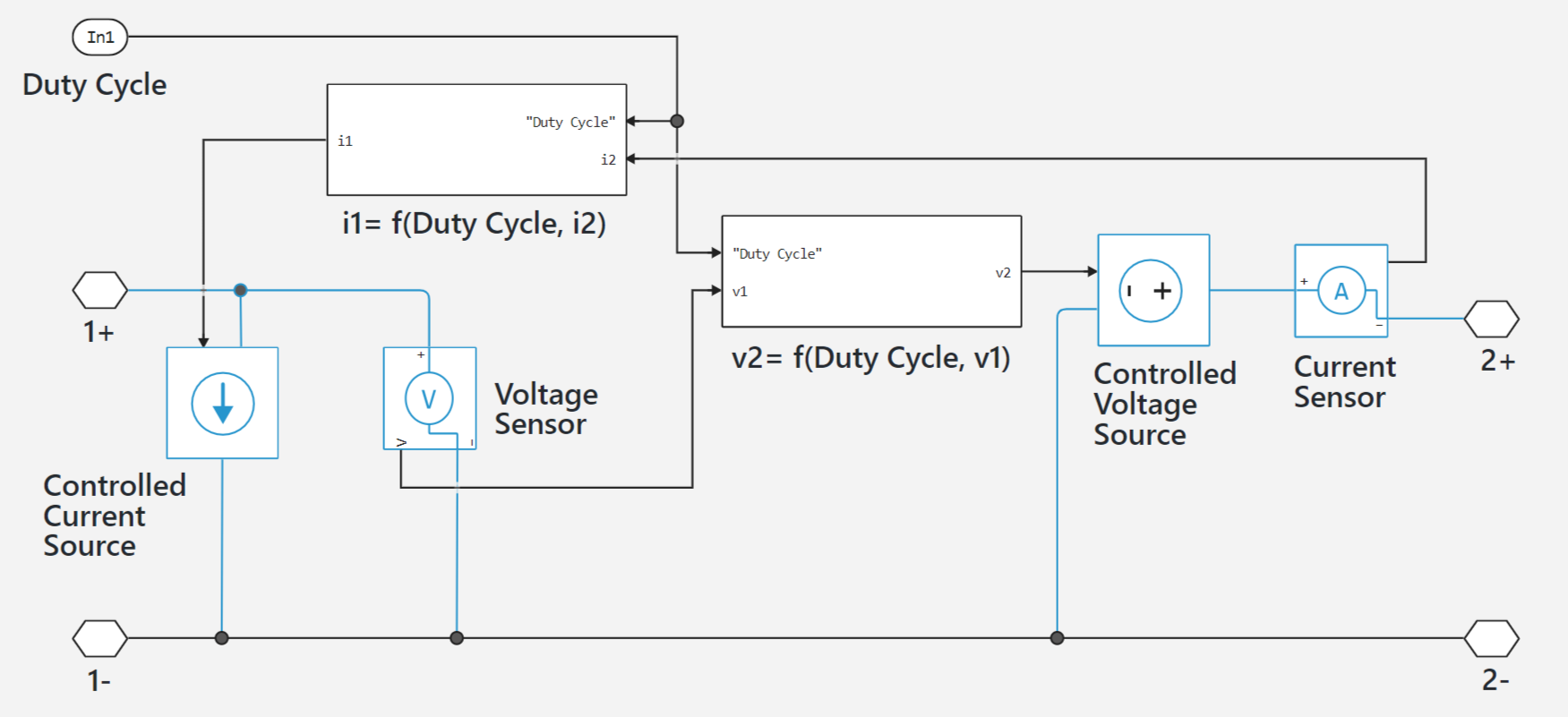
The Average-Value DC-DC Converter unit is an average-value DC-DC converter. Depending on the value of the Duty cycle parameter, it can operate as a step-down, step-up or step-down-to-step-up converter. The figure shows the equivalent circuit of the unit with duty cycle as the control signal. The converter contains a controlled current source and a controlled voltage source. Use duty cycle, reference current or reference voltage as the control input to convert electrical power between the connected components on either side of the inverter.
Equations
If you set the Control input parameter to Duty cycle, the input current and output voltage are a function of duty cycle and depend on the inverter type.
| Converter type | Output voltage, | Input current, |
|---|---|---|
Buck |
|
|
Boost |
|
|
Buck-Boost |
|
|
If Control input is set to Current reference', the inverter relates the input signal to the output current and calculates the voltage.
If the Control input is set to `Voltage reference, the inverter relates the input signal to the output voltage and calculates the current.
Ports
Non-directional
1+ - left positive terminal
scalar
Electrical port associated with the positive terminal of the first DC voltage.
1- - left negative terminal
scalar
Electrical port associated with the negative terminal of the first DC voltage.
2+ is the right positive terminal
scalar
Electrical port associated with the positive terminal of the second DC voltage.
2- is the right negative terminal
scalar
Electrical port associated with the negative terminal of the second DC voltage.
Input
DutyCycle - duty cycle
scalar
Port associated with the inverter duty cycle.
Dependencies
To enable this port, set Control Input to `Duty Cycle'.
Iref is the current reference port
scalar
A port associated with the output current value.
Dependencies
To enable this port, set the Control Input parameter to Current reference.
Vref is the voltage reference port
scalar
A port associated with the value of the output voltage.
Dependencies
To enable this port, set the Control Input parameter to Voltage reference.
Parameters
Control input - control input
Duty cycle (by default) | Current reference | Voltage reference
Specify the type of control input for conversion of electrical energy between two poles.
Converter type - type of converter
Buck converter (by default) | Buck-boost converter | Boost converter | Boost converter
Specify the converter type.
Dependencies
To enable this parameter, set Control Input to Duty Cycle.
Converter efficiency - Converter efficiency characteristic
Constant (By default) | Tabulated.
Specify the converter efficiency characteristic.
When Tabulated is set, the conduction loss will depend on the output current provided.
| Extrapolation by nearest neighbour method is used to calculate the efficiency from the data in the table. Therefore, the efficiency cannot be higher than the highest or lower than the lowest value in the Efficiency vector (%). |
Efficiency (%) is the efficiency of the inverter
100 (By default) | scalar
Inverter efficiency in per cent.
Dependencies
To enable this parameter, set Converter efficiency to Constant.
Output current vector - output current vector
[0, 2, 5] A (by default) | row vector of at least two elements.
Output current vector.
Dependencies
To enable this parameter, set Converter efficiency to Tabulated.
Efficiency vector (%) - efficiency vector
[90, 95, 98] (by default) | `row vector of at least two elements'.
The efficiency vector for each output current specified in the Output current vector parameter, in per cent.
This parameter must have the same number of elements as the output current vector.
Dependencies
To enable this parameter, set Converter efficiency to Tabulated.