Fractional Clock Divider with DSM
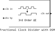
A clock frequency divider based on a delta sigma modulator.
blockType: SubSystem
|
Path in the library: |
Description
Using the delta sigma method ( ) modulations, block Fractional Clock Divider with DSM reduces the main fractional parasitic components, expanding the range in which the value on the div by port changes. This unit allows for delta sigma modulation up to the 4th order.
Ports
Input
#
clk in
—
input clock frequency
scalar
Details
The input clock frequency to be divided is given as a scalar. In the phase-locked frequency (PLL) system, the clk in port is connected to the output port of the unit Ring Oscillator VCO.
| Data types |
|
| Complex numbers support |
I don’t |
#
div by
—
the ratio of output and input clock frequencies
scalar
Details
The ratio of the output and input clock frequencies, specified as a fractional scalar. Value on the port, the div by is divided into two parts: the whole part and the fractional part .
For Delta-sigma modulator The -th order value on the port div by is achieved by changing between different integer values.
| For Delta-sigma modulator -th order use the value on the div by port. |
| Data types |
|
| Complex numbers support |
I don’t |
Output
#
clk out
—
Output clock frequency
scalar
Details
The output clock frequency returned as a scalar. In the PLL system, the clk out port is connected to the feedback Input of the unit PFD. The output signal of the clk out port is a sequence of rectangular pulses with an amplitude of 1 V.
| Data types |
|
| Complex numbers support |
I don’t |
Parameters
Parameters
#
Delta Sigma Modulator order —
The order of the delta-sigma modulator
1st order | 2nd order | 3rd order | 4th order
Details
The order of the delta-sigma modulator.
For Delta-sigma modulator The -th order value on the port div by is achieved by changing the value of the counter between different values. The order of the modulator determines the range of values into which the signal will be divided on the clk in port, providing a division effect similar to the value on the div by port.
| Values |
|
| Default value |
|
| Program usage name |
|
| Tunable |
No |
| Evaluatable |
Yes |
# Enable increased buffer size — increasing the buffer size
Details
Check this box to enable buffer size increase during simulation. This will increase the block buffer size Logic Decision inside the block Fractional Clock Divider with DSM. This check box is unchecked By default.
| Default value |
|
| Program usage name |
|
| Tunable |
No |
| Evaluatable |
Yes |
# Buffer size — the number of input buffering samples available during the simulation
Details
The number of input buffering samples available during the simulation, specified as a positive integer scalar. This value specifies the buffer size for the block Logic Decision inside the block Fractional Clock Divider with DSM.
The choice of different simulation solvers or sampling strategies can change the number of input samples required to obtain an accurate output sample. Set the buffer size large enough so that the input buffer contains all the necessary input samples.
Dependencies
To use this option, select the check box Enable increased buffer size.
| Default value |
|
| Program usage name |
|
| Tunable |
No |
| Evaluatable |
Yes |
Additional Info
Inside the mask
Details
Subsystem block Fractional Clock Divider with DSM It consists of four delta sigma modulators from the first to the fourth orders, encapsulated in the variant subsystem DSM Selector. The output signal of the DSM Selector controls the unit Single Modulus Prescaler. With the specified parameter value Delta Sigma Modulator order The corresponding delta sigma modulator is activated.
The order of the modulator determines the range in which the counter value changes. . For the Delta sigma modulator -th order value varies within different values. This change is achieved by integrating the changes in the fractional part. compared to the previous cycle and quantization of differential changes.
The general form of the transfer function for a delta sigma modulator - th order:
where
-
— the output signal of the modulator;
-
— the input signal of the modulator;
-
— quantization error.
Meaning calculated by subtracting the value of the input signal in the current cycle from its value in the previous cycle. In other words, It is a form of digital high-pass filter.
Higher-order modulators reduce the main fractional parasitic components by alternating in a wider range of integer values. As a result, the fractional parasitic components are shifted to higher frequencies in the frequency spectrum and can be filtered out more efficiently using a filter in the PLL loop.
For example, if a third-order delta sigma modulator is activated, it varies within 8 different values, which can vary from before .
| Modulator order | Range | Sequence The modulator |
|---|---|---|
1st |
|
|
2nd |
|
|
3rd |
|
|
4th |
|
|