MUSIC Spectrum
Two-dimensional MUSIC spatial spectrum estimator.
blockType: MUSICSpectrum
|
Path in the library: |

Description
Block MUSIC Spectrum Uses the MUltiple SIgnal Classification (MUSIC) algorithm to estimate the spatial spectrum of incoming narrowband signals.
The block additionally calculates the direction of arrival of a given number of signals, finding the peaks of the spectrum.
Ports
Entrance
Port 1 — received pass signal:q[<br>] complex matrix M by N | real matrix M by N
The input signal is defined as an M by N matrix, where M is the number of signal samples, and N is the number of antenna elements in the array.
Data types: Float16, Float32, Float64, Int8, Int16, Int32, Int64, UInt8, UInt16, UInt32, UInt64, Bool
Support for complex numbers: Yes
Output
Y is a two—dimensional spatial spectrum of
non-negative real matrix P by Q
The two-dimensional spatial spectrum of MUSIC, returned as a non-negative real matrix P by Q.
Each record represents the value of the estimated spatial spectrum of MUSIC. Each entry corresponds to the angle set by the Azimuth scan angles (deg) and Elevation scan angles (deg) parameters.
P is equal to the length of the vector specified in the Azimuth scan angles (deg) parameter, and Q is equal to the length of the vector specified in the Elevation scan angles (deg) parameter.
Data types: Float16, Float32, Float64, Int8, Int16, Int32, Int64, UInt8, UInt16, UInt32, UInt64, Bool
Ang — directions of arrival of pass signals:q[<br>] non-negative real matrix 2 on L
The directions of arrival of the signals returned as a real matrix 2 by L.
L is the number of signals specified by the Number of signals parameter. The angle of the arrival direction is determined by the angles of the azimuth and elevation of the source relative to the local coordinate system of the array. The first row of the matrix contains azimuth angles, and the second row contains elevation angles. If the object cannot detect peaks in the spectrum, it will return NaN.
The units of measurement of angles are degrees.
Dependencies
To use this port, check the box for the Enable DOA output option.
Data types: Float16, Float32, Float64, Int8, Int16, Int32, Int64, UInt8, UInt16, UInt32, UInt64, Bool
Parameters
Main
Signal propagation speed (m/s) — signal propagation speed, m/s
3e8 (default) | positive scalar
The propagation velocity of the signal in the form of a real positive scalar. The default value for the speed of light is `3e8 m/s'.
The units of measurement are m/s.
Data types: Float16, Float32, Float64, Int8, Int16, Int32, Int64, UInt8, UInt16, UInt32, UInt64
Operating frequency (Hz) — operating frequency of the pass sy\$
\$ 3e8 (default) | positive scalar
The operating frequency of the system, set as a positive scalar.
The units of measurement are hertz.
Data types: Float16, Float32, Float64, Int8, Int16, Int32, Int64, UInt8, UInt16, UInt32, UInt64, Bool
Forward-backward averaging — enable forward-backward averaging
disabled (by default) | enabled
Select this option to use forward-backward averaging to estimate the covariance matrix for arrays of antenna elements with a conjugate-symmetric array structure.
Azimuth scan angles (deg) — Azimuth scan angles as:q[<br>]-90:90 (default) | real scalar | real vector
Azimuth scanning angles, set as a real vector. The angle values are indicated in ascending order and must be between -180° and 180° inclusive.
The units of measurement are degrees.
Elevation scan angles (deg) — elevation scan angles as:q[<br>]0 (default) | real scalar | real vector
The angles of the height scan, set as a scalar or a vector of rows with real values. The angle values are indicated in ascending order and must be in the range from -90° to 90° inclusive.
The units of measurement are degrees.
Enable DOA output — output arrival directions via the pass output port:q[<br>] disabled (by default) | enabled
Select this option to display the arrival directions of incoming signals (DOA) via the Ang output port.
Number of signals — expected number of incoming pass signals:q[<br>] 1 (default) | positive integer
Specify the expected number of signals to estimate the arrival directions of incoming signals (DOA) as a positive integer scalar number.
Dependencies
To use this option, select the Enable DOA output checkbox.
Sensor Array
Specify sensor array as — method for specifying the pass array:q[<br>] Array (no subarrays)
The method for setting the array specified as `Array (no subarrays)'.
-
`Array (no subarrays)'— the block parameters are used to specify the array.
Element
Element type — types of antenna array elements
Isotropic Antenna (default) | Cardioid Antenna | Cosine Antenna | Custom Antenna | Gaussian Antenna | Sinc Antenna | Omni Microphone | Custom Microphone
The type of antenna array element.
Available values:
-
Isotropic Antenna -
Cardioid Antenna -
Cosine Antenna -
Custom Antenna -
Gaussian Antenna -
Sinc Antenna -
Omni Microphone -
Custom Microphone
Operating frequency range (Hz) — operating frequency range of the pass antenna array element:q[<br>] [0,1e20] (default) | a real vector is a 1 by 2 row
The range of operating frequencies of the antenna array element in the form of a vector row 1 by 2 in the form of [LowerBound,UpperBound]. The element has no response outside this frequency range. The units of frequency measurement are Hz.
Dependencies
To use this parameter, set the Element type parameter to Isotropic Antenna, Cosine Antenna, or 'Omni Microphone'.
Baffle the back of the element — accounting for radiation through the rear beam of the radiation pattern into the rear hemisphere of the Isotropic Antenna element or Omni Microphone'
`disabled (by default) | enabled
`disabled (by default)
Set this flag to exclude radiation to the rear hemisphere. The response from the rear hemisphere at all azimuth angles outside the ±90° range from the wide side is set to zero. The wide-angle direction is defined as the azimuth angle of 0° and the elevation angle of 0°.
Dependencies
To use this parameter, set the Element type parameter to Isotropic Antenna or `Omni Microphone'.
Null axis direction — the direction of the axis along the zero radiation.
-x (default) | +x | +y | -y | +z | -z
The direction of the axis is along the zero radiation.
Dependencies
To use this parameter, set the Element type parameter to Cardioid Antenna.
Exponent of cosine pattern — exponent exponent when defining the shape of a cosine radiation pattern
[1.5, 1.5] (default) | non-negative scalar | a real matrix of non-negative values of 1 by 2
The exponent of the exponent of the cosine model in the form of a non-negative scalar or a 1 by 2 real matrix of non-negative values. If the Exponent of cosine pattern is a 1 by 2 vector, then the first element is the exponent in the direction of the azimuth, and the second is in the direction of the angle of the place. With a scalar value of this parameter, the cosines in the azimuthal and elevation directions are raised to one power.
Dependencies
To use this parameter, set the Element type parameter to `Cosine Antenna'.
Operating frequency vector (Hz) — array of operating frequencies of the antenna array element
[0,1e20] (default) | real vector is a string
An array of operating frequencies of an antenna array element in the form of a row vector 1 on increasing actual values. The element has no response beyond the frequency range specified by the minimum and maximum elements of this vector. The units of frequency measurement are Hz.
Dependencies
To use this parameter, set the Element type parameter to Custom Antenna or `Custom Microphone'. To set the responses at these frequencies, use the Frequency responses (dB) parameter.
Frequency responses (dB) — frequency responses of the antenna array element
[0,0] (default)| real vector string
The frequency response of the user elements of the antenna arrays is determined by the parameter Operating frequency vector (Hz). The dimensions of the Frequency responses (dB) vector must match the dimensions of the vector specified by the Operating frequency vector (Hz) parameter.
Dependencies
To use this parameter, set the Element type parameter to Custom Antenna or `Custom Microphone'.
Input Pattern Coordinate System — selection of the coordinate system of the radiation pattern of the user antenna
az-el (default) | phi-theta
The choice of the coordinate system of the radiation pattern of the user antenna is indicated by az-el or phi-theta'. When selecting `az-el, the Azimuth angles (deg) and Elevations angles (deg) parameters are used to set the coordinates of the directional pattern points. When specifying the phi-theta parameter, the Phi angle (deg) and Theta angles (deg) parameters are used to set the coordinates of the part points.
Dependencies
To use this parameter, set the Element type parameter to Custom Antenna.
Azimuth angles (deg) — azimuth angles of the antenna radiation pattern
[-180:180] (default) | real vector is a string
The values of the azimuth angles, which will be used to calculate the antenna pattern in the form of a vector row 1 on . it must be more than 2. The azimuth angles should be in the range of −180° up to 180° inclusive and arranged in strictly ascending order.
Dependencies
To use this parameter, set the Element type parameter to Custom Antenna and the Input Pattern Coordinate System parameter to az-el.
Elevation angles (deg) — values of the angles of the antenna pattern position
[-90:90] (default) | real vector is a string
The values of the angles of the location at which it is necessary to calculate the radiation pattern in the form of a vector 1 on . it must be more than 2. The units of measurement of angles are degrees. Elevation angles should be in the range of −90° to 90° inclusive and arranged in strictly ascending order.
Dependencies
To use this parameter, set the Element type parameter to Custom Antenna and the Input Pattern Coordinate System parameter to az-el.
Phi Angles (deg) — values of the Phi angles of the antenna radiation pattern
[0:360] (default) | real vector is row 1 on P
The angular coordinates of the Phi points where the antenna radiation pattern is set. They are defined as a real vector-row 1 on . it must be more than 2. The units of measurement of angles are degrees. The values of the Phi angles should be in the range from 0° to 360° and arranged in strictly ascending order.
Dependencies
To use this parameter, set the Element type parameter to Custom Antenna and the Input Pattern Coordinate System parameter to phi-theta.
Theta Angles (deg) — values of the angles of the Theta radiation pattern of the antenna
[0:180] (default) | real vector-row 1 on Q
The angular coordinates of the Theta points where the antenna radiation pattern is set. They are defined as a real vector-row 1 on . it must be more than 2. The units of measurement of angles are degrees. The values of the Theta angles must range from 0° to 180° and be arranged in strictly ascending order.
Dependencies
To use this parameter, set the Element type parameter to Custom Antenna and the Input Pattern Coordinate System parameter to phi-theta.
Magnitude pattern (dB) — the magnitude of the antenna radiation pattern
zeros(181.361) (default) | real matrix Q on P | real array Q on P on L
The value of the antenna pattern, set as a matrix on or an array on on .
-
If the Input Pattern Coordinate System parameter is set to `az-el', then is equal to the length of the vector defined by the Elevation angles (deg) parameter, in turn, — the length of the vector defined by the Azimuth angles (deg) parameter.
-
If the Input Pattern Coordinate System parameter is set to `phi-theta', then is equal to the length of the vector defined by the parameter Theta Angles (deg), in turn, — the length of the vector defined by the Phi Angles (deg) parameter.
Value is equal to the value of the Operating frequency vector (Hz) parameter.
-
If the value of this parameter is a matrix on , then the same scheme is applied for all frequencies specified in the parameter Operating frequency vector (Hz).
-
If the value is an array on on , each element on The array defines a template for the corresponding frequency specified in the parameter Operating frequency vector (Hz).
Dependencies
To use this parameter, set the Element type parameter to Custom Antenna.
Phase pattern (deg) — phase of the radiation pattern of the user antenna
zeros(181,361) (default) | real matrix Q on P | real array Q on P on L
The phase radiation pattern of the combined antenna, defined as a matrix on or an array on on .
-
If the Input Pattern Coordinate System parameter is set to `az-el', then is equal to the length of the vector defined by the Elevation angles (deg) parameter, in turn, — the length of the vector defined by the Azimuth angles (deg) parameter.
-
If the Input Pattern Coordinate System parameter is set to `phi-theta', then is equal to the length of the vector defined by the parameter Theta Angles (deg), in turn, — the length of the vector defined by the Phi Angles (deg) parameter.
Value is equal to the value of the Operating frequency vector (Hz) parameter.
-
If the value of this parameter is a matrix on , then the same scheme is applied for all frequencies specified in the parameter Operating frequency vector (Hz).
-
If the value is an array on on , each element on The array defines a template for the corresponding frequency specified in the parameter Operating frequency vector (Hz).
Dependencies
To use this parameter, set the Element type parameter to Custom Antenna.
Align element normal with array normal — align the normal of the antenna array element relative to the grid normal
enabled (by default) | disabled
If the parameter value is enabled, the radiation pattern of the antenna element is rotated to align with the normal of the array. If it is off, then the drawing of the element does not rotate.
If the antenna is used in an antenna array and the Input Pattern Coordinate System parameter has the value az-el, checking this box rotates the radiation pattern so that the x-axis of the element coordinate system points along the normal of the array. If there is no selection, the element template is used without rotation.
If the antenna is used in an antenna array and the Input Pattern Coordinate System parameter has the value phi-theta, checking this box rotates the radiation pattern so that the z axis of the element coordinate system points along the normal of the array.
Use this parameter together with the Array Normal parameter of the URA and UCA arrays.
Dependencies
To use this parameter, set the Element type parameter to Custom Antenna.
Radiation pattern beamwidth (deg) — the beam width of the antenna pattern
[10, 10] (default) | real scalar | a real vector is a 1 by 2 row
The beam width of the antenna pattern in degrees.
Dependencies
To use this parameter, set the Element type parameter to Gaussian Antenna.
Polar pattern frequencies (Hz) — frequency values for the polar pattern of the microphone
1e3 (default) | real scalar | real vector-row 1 on L
The frequency values for the polar radiation pattern are set as a real scalar or a real vector-row 1 on . The frequencies are in the frequency range specified by the parameter Operating frequency vector (Hz).
Dependencies
To use this parameter, set the Element type parameter to Custom Microphone.
Polar pattern angles (deg) — angle values for the polar radiation pattern of the microphone
[-180:180] (default) | real vector-row 1 on P
The angle values for the polar radiation pattern of the microphone are set as a vector . The angles are measured from the central axis of the microphone and should be in the range of −180° to 180° inclusive.
Dependencies
To use this parameter, set the Element type parameter to Custom Microphone.
Polar pattern (dB) — polar directional pattern of the microphone
zeros(1,361) (default) | real vector-row 1 on L
Set the value of the polar radiation pattern of the user microphone element in the form of a real vector-row 1 on , where — the number of frequencies specified in the parameter Polar pattern frequencies (Hz). The string represents the value of the polar radiation pattern measured at the corresponding frequency specified in the Polar pattern frequencies (Hz). The radiation pattern is measured in the azimuthal plane. In the azimuthal plane, the elevation angle is 0°, and the central axis is 0° in azimuth and 0° in elevation. The polar radiation pattern is symmetrical around the central axis. Based on the polar diagram, it is possible to construct a microphone directional pattern in three-dimensional space.
Dependencies
To use this parameter, set the Element type parameter to Custom Microphone.
Array Parameters
Geometry — geometry of the pass array:q[<br>]ULA (default) | URA | UCA | Conformal Array
The geometry of the array, specified as one of:
-
'ULA' – uniform linear array,
-
URAis a uniform rectangular array, -
'UCA' – uniform circular array,
-
`Conformal Array' – arbitrary arrangement of elements.
Number of elements — number of elements of the pass antenna array:q[<br>] 2 for ULA arrays and 5 for UCA arrays (default) | an integer greater than or equal to 2
The number of ULA antenna elements, set as an integer greater than or equal to 2.
Dependencies
To enable this parameter, set the Geometry parameter to ULA or `URA'.
Element spacing (m) — distance between antenna elements in the pass array:q[<br>] 0.5 for ULA arrays (default) | positive scalar for ULA arrays | two-element vector of positive values for URA arrays
The distance between adjacent antenna elements:
-
'ULA` — indicate the distance between two adjacent antenna elements in the form of a positive scalar.
-
URA' — the distance is set as a positive scalar or a vector of positive values 1 by 2. If Element spacing (m) is a scalar, then the distances between rows and columns are equal. If Element spacing(m) is a vector, then the vector has the form `[SpacingBetweenArrayRows,SpacingBetweenArrayColumns].
Dependencies
To enable this parameter, set the Geometry parameter to ULA or `URA'.
Array axis — direction of the ULA pass linear axis:q[<br>] y (default) | x | z
The direction of the ULA linear axis, set as y, x or z. All elements of the ULA antenna array are evenly distributed along this axis in the local antenna coordinate system.
Dependencies
To enable this parameter, set the Geometry parameter to ULA.
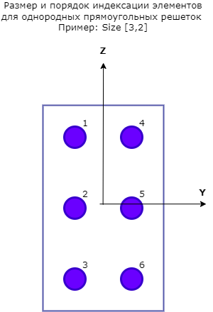
Array size — dimensions of the URA pass array:q[<br>][2,2] (default) | positive integer | vector of positive integers 1 by 2
The dimensions of the URA array, specified as a positive integer or a vector of 1 by 2 positive integers.
-
If the Array size parameter is a 1 by 2 vector, then the vector has the form [NumberOfArrayRows,NumberOfArrayColumns].
-
If the Array size parameter is an integer, then the array has the same number of elements in each row and column.
For URA, the array elements are indexed from top to bottom in the leftmost column of the array and then in the following columns from left to right.
In this figure, the array size value [3,2] creates an array with three rows and two columns.
Dependencies
To enable this parameter, set the Geometry parameter to `URA'.
Element lattice — grid of positions of URA pass elements:q[<br>]Rectangular (default) | Triangular
A grid of URA element positions, defined as rectangular or triangular.
-
Rectangularis a rectangular grid that aligns all elements in the directions of rows and columns. -
'Triangular` is a triangular grid that shifts the elements of an even row of a rectangular grid towards the positive direction of the row axis. The offset is half the distance between the elements according to the size of the row.
Dependencies
To enable this parameter, set the Geometry parameter to `URA'.
Array normal — the direction of the normal of the pass array:q[<br>]x for URA arrays or z for UCA arrays (default)| y
The normal direction of the array, specified as x, y, or z.
The elements of flat arrays lie in a plane orthogonal to the selected direction of the array normal. The side view directions of the elements are directed along the direction of the array normal.
| The value of the Array normal parameter | Element positions and aiming directions |
|---|---|
x |
The elements of the array lie in the yz-plane. All the sight vectors of the elements are directed along the x axis. |
y |
The elements of the array lie in the zx plane. All the sight vectors of the elements are directed along the y axis. |
z |
The elements of the array lie in the xy plane. The sight vectors of all the elements are directed along the z axis. |
Dependencies
To enable this parameter, set the Geometry parameter to URA or `UCA'.
Taper — changing the radiation pattern of the elements of the antenna array
1 (default) | complex scalar | complex vector
The change in the radiation pattern of the antenna array elements is set as a complex scalar or a complex vector 1 by , where — the number of antenna array elements.
The coefficients that change the radiation pattern, also called element weights, multiply the responses of the antenna array elements. The coefficients change both the amplitude and the phase of the response to reduce the side lobes or the direction of the main axis of the response.
If the value of the Taper parameter is a scalar, then the same weight is applied to each element. If Taper is a vector, then a weight from the vector is applied to the corresponding element of the antenna array. The number of scales must correspond to the number of antenna array elements.
Element positions (m) — positions of the elements of the conformal lattice
[0; 0; 0] ( by default) | a 3-by-N real matrix
The positions of the elements in the conformal array, specified as a matrix of real values 3 by N, where N is the number of elements in the conformal array.
Each column of this matrix represents the position [x; y; z] of an array element in the local coordinate system of the array. The origin of the local coordinate system is (0, 0, 0).
The units of measurement are meters.
Data types: Float16, Float32, Float64, Int8, Int16, Int32, Int64, UInt8, UInt16, UInt32, UInt64, Bool
Dependencies
To enable this parameter, set the Geometry parameter to `Conformal Array'.
Element normals (deg) is the direction of the normal vectors of the elements of the conformal lattice
[0; 0] | ` column vector 2 by 1` | matrix 2 by N
The direction of the normal vectors of elements in a conformal array, defined as a 2-by-1 column vector or a 2-by-N matrix.
N indicates the number of elements in the array.
If the parameter is a matrix, each column specifies the direction of the normal of the corresponding element in the form of [azimuth;elevation] relative to the local coordinate system. The local coordinate system aligns the positive x-axis with the direction of the normal to the conformal array.
If the parameter value is a 2-by-1 column vector, the same pointing direction is used for all array elements.
Parameters of Element positions (m) and Element normals (deg) can be used to represent any arrangement in which pairs of elements differ by certain transformations.
Transformations can combine translation, azimuth rotation, and elevation rotation. However, transformations that require rotation relative to the normal direction cannot be used.
Data types: Float16, Float32, Float64, Int8, Int16, Int32, Int64, UInt8, UInt16, UInt32, UInt64, Bool
Dependencies
To enable this parameter, set the Geometry parameter to `Conformal Array'.