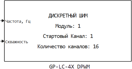
GP-LC-4X DPWM
Setting PWM on discrete pins GP-LC-4X using output DMA.
blockType: SubSystem
|
Path in the library: |
Description
| To work with the block, install/update the support package RITM blocks. |
Block GP-LC-4X DPWM It is used to set PWM on discrete pins GP-LC-4X using output DMA.
| When using the block GP-LC-4X DPWM the ability to use the block is lost GP-LC-4x DO on this I/O module, even on unused channels. |
| When using high-frequency periodic signal generation units on a specific analog output channel of the I/O module RITMeX GP-LC-4X, it will no longer be possible to use other high-frequency periodic signal generation units on another channel of this module. |
| When changing the parameters of the signal at low frequencies (up to 1kHz), the change in the waveform takes effect after 1-2 periods of this signal. When changing the parameters of the signal at high frequencies, the changes take effect in at least 1 ms and no more than 2 ms. The process of changing the waveform does not affect the TET of the block. |
Ports
Input
#
Frequency, Hz
—
signal frequency for all digital output channels involved
scalar
Details
| Data types |
|
| Complex numbers support |
No |
#
Borehole
—
The PWM borehole is in the form of an array, which should have a size equal to the number of channels involved.
vector
Details
Borehole refers to the ratio of the signal period to the pulse duration.
| Data types |
|
| Complex numbers support |
No |
Parameters
| All the parameters listed except the last three specify the waveform only during initialization. If at the first calculation step the corresponding parameters at the inputs of the block are different, then the waveform will be changed. |
Main group
# Частота (10-100000 Гц): — the initial frequency of the signal for all digital output channels involved
Details
| Default value |
|
| Program usage name |
|
| Tunable |
No |
| Evaluatable |
Yes |
# Скважность: — The initial PWM borehole is in the form of an array, which should have a size equal to the number of channels involved.
Details
| Default value |
|
| Program usage name |
|
| Tunable |
No |
| Evaluatable |
Yes |
#
Стартовый канал: —
the first digital output channel used
1 | 2 | 3 | 4 | 5 | 6 | 7 | 8 | 9 | 10 | 11 | 12 | 13 | 14 | 15 | 16
Details
| Values |
|
| Default value |
|
| Program usage name |
|
| Tunable |
No |
| Evaluatable |
Yes |
# Количество каналов (1-16): — number of digital output channels involved
Details
| Default value |
|
| Program usage name |
|
| Tunable |
No |
| Evaluatable |
Yes |
#
Номер модуля: —
unique identification of the module
1 | 2 | 3 | 4 | 5 | 6 | 7 | 8
Details
It is used when more than one I/O module of the same type is installed in a real-time machine.
| Values |
|
| Default value |
|
| Program usage name |
|
| Tunable |
No |
| Evaluatable |
Yes |
# Шаг расчета, с: — The calculation step is to send the samples to digital channels exiting the real-time application
Details
| Default value |
|
| Program usage name |
|
| Tunable |
No |
| Evaluatable |
Yes |