GP-LC-4X PWM
Setting the PWM to the DAC GP-LC-4X using the output DMA.
blockType: SubSystem
|
Path in the library: |
Description
| To work with the block, install/update the support package RITM blocks. |
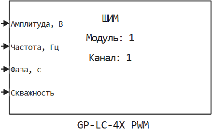
Block GP-LC-4X PWM used to set the PWM to the DAC GP-LC-4X using the output DMA.
Ports
Input
#
The amplitude, In
—
signal amplitude
scalar
Details
| Data types |
|
| Complex numbers support |
No |
#
Frequency, Hz
—
signal frequency
scalar
Details
| Data types |
|
| Complex numbers support |
No |
#
Phase, with
—
signal phase in seconds
scalar
Details
| Data types |
|
| Complex numbers support |
No |
#
Borehole
—
PWM borehole
scalar
Details
Borehole refers to the ratio of the signal period to the pulse duration.
| Data types |
|
| Complex numbers support |
No |
Parameters
| All the parameters listed except the last three specify the waveform only during initialization. If at the first calculation step the corresponding parameters at the inputs of the block are different, then the waveform will be changed. |
Main group
# Амплитуда (0-5 В): — initial amplitude during signal initialization
Details
| Default value |
|
| Program usage name |
|
| Tunable |
No |
| Evaluatable |
Yes |
# Скважность:: — initial duty cycle of the PWM
Details
| Default value |
|
| Program usage name |
|
| Tunable |
No |
| Evaluatable |
Yes |
# Частота (500-13000 Гц): — the initial frequency of the signal
Details
| Default value |
|
| Program usage name |
|
| Tunable |
No |
| Evaluatable |
Yes |
# Фаза, c: — the initial phase of the signal in seconds
Details
| Default value |
|
| Program usage name |
|
| Tunable |
No |
| Evaluatable |
Yes |
#
Номер модуля: —
unique identification of the module
1 | 2 | 3 | 4 | 5 | 6 | 7 | 8
Details
It is used when more than one I/O module of the same type is installed in a real-time machine.
| Values |
|
| Default value |
|
| Program usage name |
|
| Tunable |
No |
| Evaluatable |
Yes |
#
Номер канала: —
the number of the analog output channel on which this signal will be generated
1 | 2
Details
| Values |
|
| Default value |
|
| Program usage name |
|
| Tunable |
No |
| Evaluatable |
Yes |
# Шаг расчета, с: — The calculation step is to send the samples to the digital channels exiting the real-time application
Details
| Default value |
|
| Program usage name |
|
| Tunable |
No |
| Evaluatable |
Yes |