Permanent Magnet DC Motor
A model of a DC motor with electrical and mechanical parameters.
blockType: AcausalElectricPowerSystems.Electromechanical.Brushed.DCMotor
|
Permanent Magnet DC Motor Path in the library: |
|
Wound DC Motor Path in the library: |


Description
The DC Motor block is represented using the following equivalent circuit:
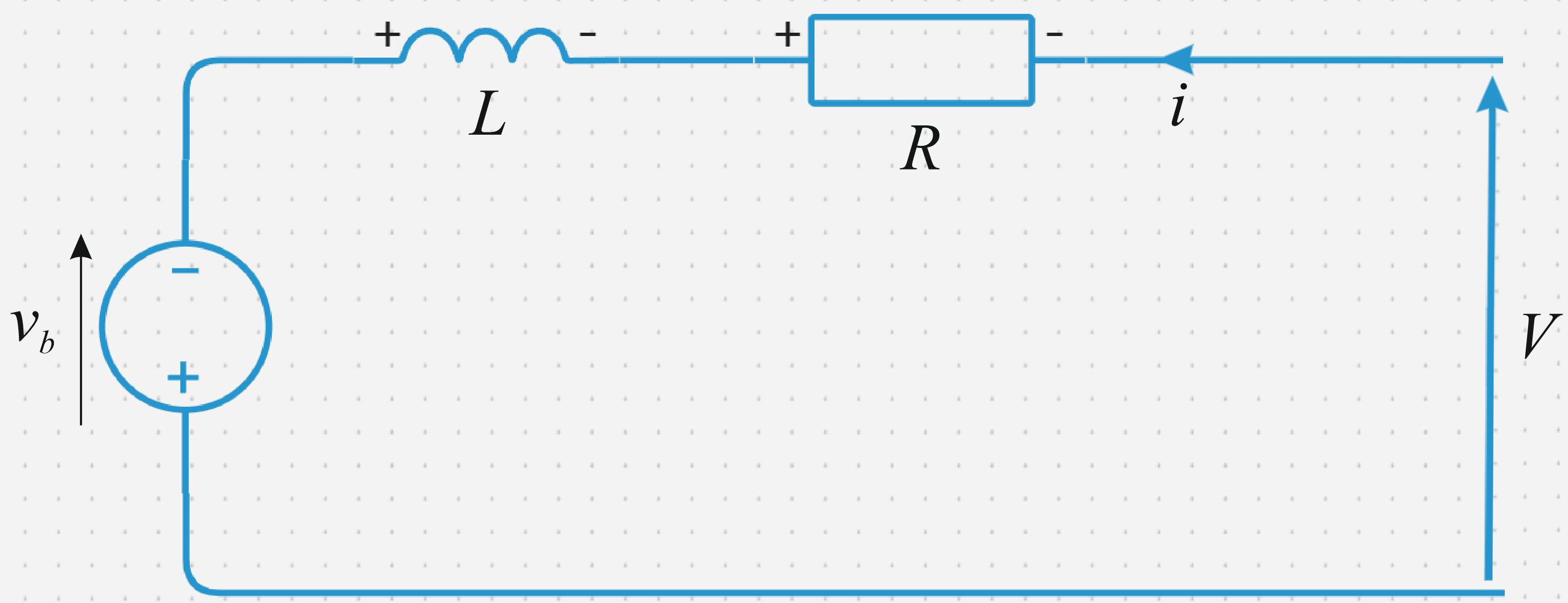
The parameters of the equivalent circuit for this model are set when the Model parameterization parameter is set to By equivalent circuit parameters. The resistor corresponds to the resistance set in the Armature resistance parameter. Inductance corresponds to the inductance specified in the Armature induction parameter.
You can specify how to create the magnetic field of the motor by setting the Field type parameter to the desired value. The permanent magnets of the motor induce an anti-EMF in the armature :
where — the EMF coefficient (the value of the parameter Back-emf constant), and — angular velocity.
The motor creates a torque which is proportional to the motor current according to the expression:
where — the constant of the moment.
In the DC motor unit, it is assumed that there are no electromagnetic losses. This means that the mechanical power is equal to the electrical power of the armature. Equating these two conditions gives:
Thus, the block parameters specify either , or .
If the magnetic field is created by the current flowing through the windings, then the Back-emf constant depends on the excitation current :
where — mutual inductance of the rotor and stator (parameter Field-armature mutual induction).
The mechanical characteristic for the DC Motor unit is related to the parameters shown in the previous figure. When setting the Model parameterization parameter to By stall torque and no-load speed or By rated load and speed, the block solves the problems for the parameters of the equivalent circuit as follows:
-
In steady state, the inductance it has no effect on the dependence of the torque from the speed .
-
The voltages in the circuit are summed up, and the expression is rewritten for :
-
Meaning it is substituted into the torque equation:
When setting the Model parameterization parameter to By stall torque and no-load speed The unit uses the torque and idle speed to determine the values and (and equivalently ).
When setting the Model parameterization parameter to By rated load and speed The unit uses the rated speed and power to calculate the rated torque. To determine the values and The unit uses the values of rated torque and idle speed.
The block simulates the inertia of the engine and damping for all values of the Model parameterization parameter. The resulting moment is:
It is not always possible to measure the rotor damping, and its value is not always indicated in the manufacturer’s technical data sheet. An alternative option is to use the no—load current to calculate the damping value of the rotor.
In idle mode, the mechanical torque generated by the electric current must be equal to the damping torque of the rotor.:
where — idle current. If the Rotor damping parameterization parameter is selected By no-load current, then this equation is used in addition to the equation of the dependence of speed on torque to determine the values of and other coefficients of the equation.
The value of the rotor damping, set directly or as an idling current, is taken into account when determining the parameters of the equivalent circuit for the Model parameterization parameters and value variants. By stall torque and no-load speed and By rated load and speed.
When a positive current flows from the electrical ports + to −, a positive moment acts from the mechanical port C to R.
Ports
+ — positive anchor contact
electricity
The electrical port corresponding to the positive contact of the armature of the DC motor.
− — negative anchor contact
electricity
The electrical port corresponding to the negative contact of the DC motor armature.
C — motor housing
rotational mechanics
A mechanical rotation port corresponding to the DC motor housing.
R — motor rotor
rotational mechanics
A mechanical rotation port corresponding to the rotor of a DC motor.
F+ — positive contact of the field winding
electricity
The electrical port corresponding to the positive contact of the excitation winding.
Dependencies
To use this port, set the Field type parameter to Wound.
F− — negative contact of the field winding
electricity
The electrical port corresponding to the negative contact of the excitation winding.
Dependencies
To use this port, set the Field type parameter to Wound.
Parameters
Electric torque
Field type — type of the pass field:q[<br>] Permanent Magnet (by default) | Wound
Choose one of the following ways to create a field:
-
Permanent Magnet— The magnetic field of a DC motor is created using a permanent magnet. -
Wound— the magnetic field of the DC motor is created by the excitation winding.
Model parameterization — type of parameterization of the pass block:q[<br>] By equivalent circuit parameters (by default) | By stall torque and no-load speed | By rated load and speed
Select one of the following block parameterization methods:
-
By equivalent circuit parameters— according to the parameters of the equivalent engine circuit. -
By stall torque and no-load speed— by starting torque and idling speed, which the unit recalculates into parameters of the equivalent circuit. -
By rated load and speed— according to the rated power and speed, which the unit recalculates into the parameters of the equivalent circuit.
Dependencies
To use this parameter, set the Field type parameter to Permanent magnet.
Field resistance — field winding resistance
100 Ohms (default)
Electrical resistance of the excitation winding.
Dependencies
To use this parameter, set the Field type parameter to Wound.
Field induction — field winding inductance
1 Gb (default)
The inductance of the excitation winding.
Dependencies
To use this parameter, set the Field type parameter to Wound.
Field-armature mutual induction — mutual inductance of the rotor and stator
0.15 Gn (default)
Mutual inductance of the rotor and stator.
Dependencies
To use this parameter, set the Field type parameter to Wound.
Initial field current — initial excitation current
0 A (default)
The initial excitation current.
Dependencies
To use this parameter, set the Field type parameter to Wound.
Armature resistance — armature resistance
3.9 Ohms (default)
Electrical resistance of the motor armature.
Dependencies
To use this parameter, set the Model parameterization parameter to By equivalent circuit parameters.
Armature induction — armature inductance
12e−6 Gn (default)
The inductance of the motor armature. If you do not have information about this inductance, set the value of this parameter to a small non-zero number.
Define back-emf or torque constant — definition of constant
Specify back-emf constant (default) | Specify torque constant
Specify which engine constant will be set: the EMF coefficient or the torque constant. When set in SI units, these constants have the same value, so you can specify only one of them in the dialog box of the block.
Dependencies
To use this parameter, set the Model parameterization parameter to By equivalent circuit parameters.
Back-emf constant — Anti-EMF pass coefficient:q[<br>] 0.000687549354157 V/(rad/s) (default)
The ratio of the EMF generated by the engine to the rotational speed of the engine.
Dependencies
To use this parameter, set the Define back-emf or torque constant parameter to Specify back-emf constant.
Torque constant — constant of torque
0.0006876 N·m/A (default)
The ratio of the torque generated by the motor to the current flowing.
Dependencies
To use this parameter, set the Define back-emf or torque constant parameter to Specify torque constant.
Stall torque — starting torque
0.00024 Nm (default)
The amount of torque generated by the engine when the rotational speed is zero.
Dependencies
To use this parameter, set Model parameterization to By stall torque and no-load speed.
No-load speed — idling speed
2000.1473 rad/s (default)
The speed of rotation of the engine without load.
Dependencies
To use this parameter, set Model parameterization to By rated load and speed.
Rated speed (at rated load) — rated pass rotation speed:q[<br>] 1570.7963 rad/s (default)
Engine speed at rated mechanical power.
Dependencies
To use this parameter, set Model parameterization to By rated load and speed.
Rated load (mechanical power) — rated pass load:q[<br>] 0.08 W (default)
The mechanical power that the engine is designed for at the rated speed.
Dependencies
To use this parameter, set Model parameterization to By rated load and speed.
Rated DC supply voltage — rated DC supply voltage
1.5 V (default)
The voltage for which the rated power is set.
Dependencies
To use this parameter, set Model parameterization to By stall torque and no-load speed or By rated load and speed.
Rotor damping parameterization — parameterization of rotor damping
By damping value (by default) | By no-load current
Choose one of the following ways to set the rotor damping:
-
By damping value— setting the value of the rotor damping directly, using the Rotor damping parameter in the Mechanical group. -
By no-load current— the unit calculates the rotor damping based on the values set for the parameters No-load current and DC supply voltage when measuring no-load current. When this option is selected, the Rotor damping parameter is not available in the Mechanical group.
No-load current — no-load current
0 (default)
Specify the value of the no-load current, A, which will be used to calculate the rotor damping.
Dependencies
To use this parameter, set Rotor damping parameterization to By no-load current.
DC supply voltage when measuring no-load current — DC supply voltage when measuring no-load current
1.5 V (default)
Set the DC supply voltage corresponding to the no-load current value that will be used to calculate the rotor damping.
Dependencies
To use this parameter, set Rotor damping parameterization to By no-load current.
Mechanical
Rotor inertia — inertia of the rotor
1e−9 kg·m2 (default)
The resistance of the rotor to a change in engine speed. The value can be zero.
Rotor damping — dissipated energy of the rotor
0 (default)
The energy dissipated by the rotor, nm/(rad/s). The value can be zero.
Dependencies
To use this parameter, set the Rotor damping parameterization parameter in the Electrical Torque group to By damping.
Initial rotor speed — initial rotation speed of
0 (default)
The speed of rotation of the rotor at the beginning of the simulation, rad/s.