Integrator (Discrete or Continuous)
A discrete-time or continuous-time integrator.
blockType: SubSystem
|
Path in the library: |
Description
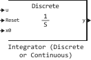
Block Integrator (Discrete or Continuous) implements a simple integrator in accordance with the IEEE 421.5-2016 standard [1].
You can switch between continuous and discrete integrator implementations using the parameter Sample time (-1 for inherited).
The equations
notable mode
To configure the integrator for continuous operation, set the parameter Sample time (-1 for inherited) meaning 0. This representation is equivalent to a continuous transfer function.:
From the above transfer function, the equations defining the integrator have the form:
where
-
— simulation time;
-
— integrator input signal;
-
— integrator output signal;
-
— condition of the integrator;
-
— the initial state of the integrator.
discret mode
To configure the integrator to work in discrete mode, set the parameter Sample time (-1 for inherited) a positive non-zero value or a value −1 to inherit the sampling period from the upstream block. The discrete representation is equivalent to the transfer function:
where — the sampling period. Based on the discrete transfer function, the integrator equations are determined using the direct Euler method:
where
-
— time step of the simulation;
-
— integrator input signal;
-
— integrator output signal;
-
— condition of the integrator;
-
— the initial state of the integrator.
Determining the initial conditions
The initial state conditions can be set using the input port x0. The state of the integrator returns to its initial state with each reset.
Limitation of the integral
The output signal of the integral can be limited in one of two ways:
-
Set for the parameter Limit type meaning
Anti-windupto use the saturation method with protection against oversaturation.The method of protection against oversaturation limits the state of the integrator the range between the lower saturation limit and the upper limit of saturation :
Since the state is limited, the output signal can immediately respond to a change in the sign of the input signal when the integral is saturated.
-
Set for the parameter Limit type meaning
Windupto use the integral saturation method.The integral saturation method limits the integrator’s output signal the range between the lower saturation limit and the upper limit of saturation :
Since the output signal is limited, the state can continue to grow when the integrator is saturated. As a result, the output signal cannot respond to a change in the sign of the input signal until the state reaches the saturation limit point.
Ports
Input
#
u
—
integrator input signal
vector
Details
Integrator input signal.
| Data types |
|
| Complex numbers support |
I don’t |
#
Reset
—
return to the original state
scalar
Details
Reset the integrator. To reset the integrator status to the port value x0, apply a non-zero value to this port. Alternatively, connect the unit to this port Constant with a value of zero to override the external reset.
| Data types |
|
| Complex numbers support |
I don’t |
#
x0
—
initial state
vector
Details
The initial state of the integrator. To set the status value after the reset, send a signal to this port.
| Data types |
|
| Complex numbers support |
I don’t |
Output
#
y
—
integrator output signal
vector
Details
The output signal of the integrator.
| Data types |
|
| Complex numbers support |
I don’t |
Parameters
Main group
#
External reset —
reset strategy
rising | falling | either | level
Details
Choose an external reset strategy for the integrator:
-
rising— The unit resets the state when the reset signal switches from a negative or zero value to a positive one. -
falling— The unit resets the state when the reset signal changes from a positive value to zero or negative. -
either— the unit resets the state when the reset signal changes from zero to a non-zero value, from a non-zero value to zero, or changes its sign. -
level— the block resets the state when the reset signal is not zero at the current time step or changes from a non-zero value at the previous time step to zero at the current time step.
| Values |
|
| Default value |
|
| Program usage name |
|
| Evaluatable |
Yes |
#
Limit type —
saturation strategy
Anti-windup | Windup
Details
Select the type of integrator constraint:
-
Anti-windup— the block restricts the state of the integrator, preventing its oversaturation. -
Windup— the block limits the output signal of the integrator, allowing the state of the integrator to be oversaturated.
| Values |
|
| Default value |
|
| Program usage name |
|
| Evaluatable |
Yes |
# Upper saturation limit — upper limit of the condition
Details
The upper limit of the integrator saturation. Set the value Inf for the unsaturated upper limit or the final value for saturation of the integrator using the strategy specified by the parameter Limit type.
| Default value |
|
| Program usage name |
|
| Evaluatable |
Yes |
# Lower saturation limit — the lower limit of the condition
Details
The lower saturation limit of the integrator. Set the value −Inf for the unsaturated lower limit or the final value for saturation of the integrator using the strategy specified by the parameter Limit type.
| Default value |
|
| Program usage name |
|
| Evaluatable |
Yes |
# Sample time (-1 for inherited) — block sampling period
Details
The time between consecutive block executions. During execution, the block generates output signals and, if necessary, updates its internal state.
For the inherited discrete time mode, set this parameter to −1. For discrete mode, set this parameter to a positive integer. For continuous mode, set this parameter to 0.
| Default value |
|
| Program usage name |
|
| Evaluatable |
Yes |