N-Channel IGBT (Advanced)
An N-channel bipolar transistor with an isolated gate.
blockType: AcausalElectricPowerSystems.Semiconductors.IGBTAdvanced
|
Path in the library: |
Description
Block N-Channel IGBT (Advanced) simulates an Insulated-Gate Bipolar Transistor (IGBT). The unit provides a complete model of volt-ampere characteristics (VAC) and capacitance characteristics, suitable for modeling detailed switching characteristics and predicting losses in a component. The block allows you to model IGBT in the following ways:
-
In the form of an equivalent circuit based on a bipolar PNP transistor and an N-channel MOSFET. For more information, see Representation as an equivalent circuit, Fine-tuning of volt-ampere characteristics and Modeling of temperature dependence.
-
In the form of a two-dimensional interpolation table of approximate VAC values. For more information, see Representation using a two-dimensional interpolation table.
-
In the form of a three-dimensional interpolation table of approximate VAC values, including temperature data. For more information, see Representation using a three-dimensional interpolation table.
In the model, the gate capacity is represented by a fixed gate-emitter capacity. and a fixed or non-linear gate collector capacity . For more information, see Charge model.
Representation as an equivalent circuit
The equivalent circuit consists of a block PNP Bipolar Transistor, controlled by the block N-Channel MOSFET as shown in the following picture.
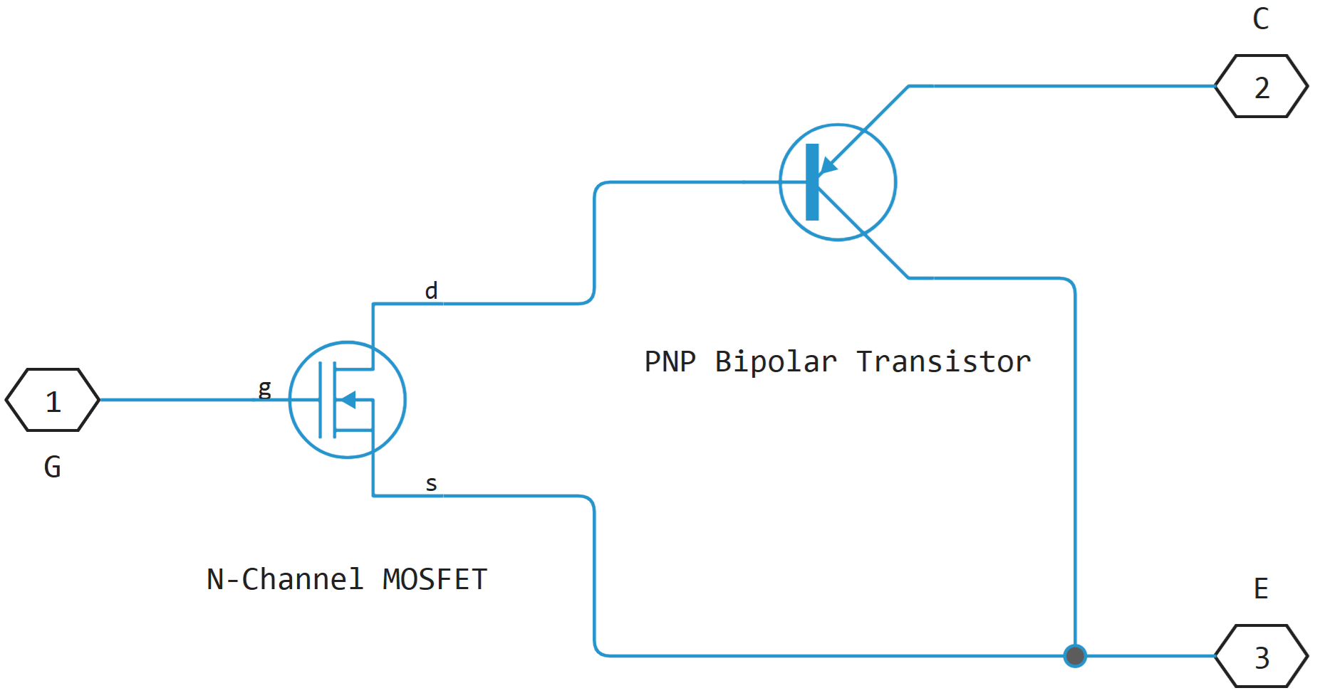
The MOSFET source is connected to the collector of a bipolar transistor, and the MOSFET drain is connected to the base of a bipolar transistor. For the MOSFET, the threshold voltage equations given in the description of the unit are used. N-Channel MOSFET. For a bipolar transistor, the equations from the block description are used PNP Bipolar Transistor with an additional emission factor , scaling .
Block N-Channel IGBT (Advanced) It uses the on and off state characteristics set in the settings to evaluate the parameters of the internal N-channel MOSFET and bipolar PNP transistors. Based on the characteristics of the off state, the unit calculates the base-emitter voltage. and saturation current .
When the transistor is turned off, the gate-emitter voltage is zero, and the base-collector IGBT voltage is high. Therefore, the equations of the base and collector currents of a PNP transistor are simplified to
where
-
— parameter value Emission coefficient, N;
-
— Earley’s tension is in the forward direction;
-
and — positive currents directed to the collector and base, respectively.
The definitions of the remaining variables are given in the description of the block. PNP Bipolar Transistor. From the first equation, we can determine .
In the off state, the base current is zero, so , where — collector current at zero gate voltage. The base-collector voltage is , where — the voltage at which it is measured . Then the second equation takes the form
The block sets typical values and , therefore and they are determined by the formulas
|
The exact value Not required: the unit adjusts the MOSFET gain to ensure the correct overall gain of the device. |
Parameters Collector-emitter saturation voltage, Vce(sat) and Collector current at which Vce(sat) is defined used to determine by solving the following equation:
After that, the unit calculates the MOSFET gain using the following equation:
where
-
— parameter value Gate-emitter threshold voltage, Vge(th);
-
— parameter value Gate-emitter voltage at which Vce(sat) is defined;
-
— parameter value Total forward transit time.
Voltage it is related to the transistor voltages by the ratio . The block substitutes this ratio instead of , sets the base-emitter voltage and base current equal to saturation values and converts the MOSFET equation to obtain
where — parameter value Collector-emitter saturation voltage, Vce(sat).
These calculations ensure that the specified collector current at zero gate voltage and collector-emitter saturation voltage are precisely matched. Volt-ampere characteristics are sensitive to the emission factor and the exact value . If the manufacturer’s technical description contains volt-ampere characteristics for different values , then the parameters and you can configure it manually.
Representation using a two-dimensional interpolation table
To represent using an interpolation table, set the tabular collector current values as functions of gate-emitter and collector-emitter voltages. The main advantage of this method is the speed of modeling. The device can be parameterized based on both measurement results and data from another simulation environment.
The tabular representation combines all the components of an equivalent circuit — a PNP transistor, an N-channel MOSFET, collector and emitter resistors - into one equivalent interpolation table.
|
To ensure that the signs of collector-emitter current and voltage are consistent, observe the following conditions:
|
Representation using a three-dimensional interpolation table
For a temperature-dependent representation using an interpolation table, set the tabular collector current values as functions of gate-emitter and collector-emitter voltages and temperature.
The tabular representation combines all the components of an equivalent circuit — a PNP transistor, an N-channel MOSFET, collector and emitter resistors - into one equivalent interpolation table.
If the thermal port of the unit is not used, the simulation temperature is set by the parameter Device simulation temperature in the parameter group Temperature Dependence.
|
To ensure that the signs of collector-emitter current and voltage are consistent, observe the following conditions:
|
Charge model
The block simulates capacitances with fixed values or tabular values depending on the collector-emitter voltage. The gate-emitter and gate-collector capacitances can be set directly, or calculated from the input and output capacitances. Parameter Parameterization in the parameter group Junction Capacitance provides the following parameterization methods:
-
Specify fixed input, reverse transfer, and output capacitance(by default) — set fixed parameter values from the technical description and convert the values of the inlet and outlet tanks to capacity values, as described below; -
Specify fixed gate-emitter, gate-collector, and output capacitance— set fixed capacity parameter values directly; -
Specify tabulated input, reverse transfer, and output capacitance— set the tabular values of the collector-emitter capacitance and voltage based on the graphs from the technical description, then convert the values of the input and output capacitances to the capacitance values as described below; -
Specify tabulated gate-emitter, gate-collector, and output capacitance— set tabular values of capacitance and collector-emitter voltage.
Use one of the tabular methods (Specify tabulated input, reverse transfer, and output capacitance or Specify tabulated gate-emitter, gate-collector, and output capacitance), if the technical description shows a graph of the dependence of the capacitance on the collector-emitter voltage. Using tabular capacity values will provide more accurate dynamic characteristics and avoid the need for iterative parameter settings.
If you use the method Specify fixed gate-emitter, gate-collector, and output capacitance or Specify tabulated gate-emitter, gate-collector, and output capacitance, then in the parameter group Junction Capacitance you can directly specify the parameter values Gate-emitter capacitance, Gate-collector capacitance and Collector-emitter capacitance. In other cases, the block calculates them based on the parameter values. Input capacitance, Cies, Reverse transfer capacitance, Cres and Output capacitance, Coes. These two parameterization methods are related as follows:
With fixed capacities (Specify fixed input, reverse transfer, and output capacitance or Specify fixed gate-emitter, gate-collector, and output capacitance) the model contains a fixed gate-emitter capacitance and a fixed or non-linear gate collector capacity . If for the parameter Charge-voltage linearity select a value Gate-collector charge function is nonlinear, the gate-collector charge dependence is determined by a piecewise linear function shown in the following figure.
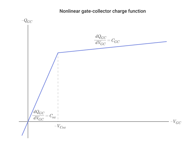
With such a nonlinear capacitance, the gate-emitter and collector-emitter voltage profiles take the shape shown in the following figure. The collector-emitter voltage drop consists of regions 2 and 3, and the gate-emitter voltage has two time constants — before and after the threshold voltage .
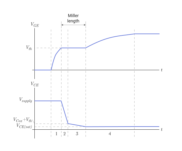
If the IGBT gate is controlled via an external resistance , capacitance values of the capacitors , and it can be defined as follows:
-
Ask so, to get the required time constant for in the 1 area. The time constant is equal to the product and . Instead, you can use the value from the technical description.
-
Ask so, to get the required gradient in the 2 area. The gradient is .
-
Ask equal to the voltage at which the gradient changes , minus the threshold voltage .
-
Ask so, to get the required Miller length and time constant in the region of 4.
The model simplifies the actual charge distribution, so several iterations of these four steps may be required to best match the measured data.
If for the parameter I-V characteristics defined by the value is set Fundamental nonlinear equations, the tail end of the collector current when the IGBT is turned off is determined by the parameter Total forward transit time.
If for the parameter I-V characteristics defined by the value is set Lookup table (2D, temperature independent) or Lookup table (3D, temperature dependent), the tail end of the collector current when the IGBT is turned off is determined by the parameter Turn-off tail current transit time:
where — IGBT shutdown current, — IGBT switching current, — shutdown time, — parameter value Turn-off tail current transit time.
| The model takes charge into account, therefore, in order to correctly reproduce the dynamics of switching on and off, it is necessary to simulate the impedance of the gate control circuit. If the control circuit is represented by a controlled voltage source, a suitable series resistor should be connected between the source and the gate. |
Fine-tuning of volt-ampere characteristics
- To represent the model as an equivalent schema, use the group parameters Advanced to fine-tune the volt-ampere characteristics of the device. Configuration requires a manufacturer’s technical description with graphs of the dependence of collector current on collector-emitter voltage at different gate-emitter voltages. These parameters have the following effects
-
-
Parameter Emission coefficient, N determines the shape of the volt-ampere characteristics near the origin;
-
Parameters Collector resistance, RC and Emitter resistance, RE they affect the slope of the VAC at higher currents and when the device is fully opened under the influence of high gate-emitter voltage;
-
Parameter Forward Early voltage, VAF affects the shape of the VAC at gate-emitter voltages near the value Gate-emitter threshold voltage, Vge(th).
-
Modeling of temperature dependence
For a two-dimensional interpolation table, the electrical equations are independent of temperature. However, the temperature dependence can be modeled using a three-dimensional table or using an equivalent scheme.
The equivalent scheme uses the temperature dependences of the constituent components. The defining equations are given in the block descriptions. N-Channel MOSFET and PNP Bipolar Transistor.
If the technical description does not contain information about collector current at zero gate voltage For a higher measurement temperature, an energy gap can be set. a typical value for a semiconductor. For silicon, the energy gap is usually 1.11 EV.
Assumptions and limitations
The model used in the block is based on the following assumptions:
-
The block does not allow you to directly set the initial conditions for the containers. If you check the box Start simulation from steady state in the block Solver Configuration, the initial voltages are calculated in accordance with the calculated steady-state mode. Otherwise, the voltages at the beginning of the simulation are zero.
-
Non-zero capacitance values may be required to avoid numerical problems, but zero values can increase the simulation speed.
-
The unit does not take into account the effect of temperature on the capacity.
Ports
Conserving
#
E
—
The emitter
electricity
Details
A non-directional port connected to the collector terminal of a PNP transistor.
| Program usage name |
|
#
G
—
the shutter
electricity
Details
A non-directional port connected to the IGBT gate terminal.
| Program usage name |
|
#
H
—
thermal port
warm
Details
Non-directional heat port.
Dependencies
To use this port, check the box Enable thermal port.
| Program usage name |
|
#
C
—
collector
electricity
Details
A non-directional port connected to the terminal of the PNP transistor emitter.
| Program usage name |
|
Parameters
Thermal Port
#
Thermal resistances, [R1, R2, ..., Rn] —
the vector of thermal resistances for the Foster model
K/W
Details
Vector from the values of thermal resistances represented by Foster elements in the heating network. All these values must be greater than zero.
Dependencies
To use this option, check the box Enable thermal port, for the parameter Thermal network set the value Cauer model parameterized with Foster coefficients.
| Units |
|
| Default value |
|
| Program usage name |
|
| Evaluatable |
Yes |
#
Thermal masses, [M1, M2, ..., Mn] —
the vector of heat capacity values for the Foster model
J/K | kJ/K
Details
Vector from values of heat capacities, where — this is the number of coefficients of the Foster model in the heating network. All these values must be greater than zero.
Dependencies
To use this option, check the box Enable thermal port, for the parameter Thermal network set the value Cauer model parameterized with Foster coefficients, and for the parameter Thermal mass parameterization — value By thermal mass.
| Units |
|
| Default value |
|
| Program usage name |
|
| Evaluatable |
Yes |
#
Thermal masses, [M1, M2, ..., Mn] —
vector of heat capacity values for the Kauer model
J/K | kJ/K
Details
Vector from values of heat capacities, where — this is the number of coefficients of the Kauer model in the heating network. All these values must be greater than zero.
Dependencies
To use this option, check the box Enable thermal port, for the parameter Thermal network set the value Cauer model, and for the parameter Thermal mass parameterization — value By thermal mass.
| Units |
|
| Default value |
|
| Program usage name |
|
| Evaluatable |
Yes |
#
Thermal time constants, [t1, t2, ..., tn] —
the vector of thermal time constants for the Foster model
s | ns | us | ms | min | hr | d
Details
Vector from values of thermal time constants, where — this is the number of Foster elements in the heating network. All these values must be greater than zero.
The value of the heat capacity is calculated as , where , and — heat capacity, thermal time constant and thermal resistance for - th Foster element.
Dependencies
To use this option, check the box Enable thermal port, for the parameter Thermal network set the value Cauer model parameterized with Foster coefficients, and for the parameter Thermal mass parameterization — value By thermal time constants.
| Units |
|
| Default value |
|
| Program usage name |
|
| Evaluatable |
Yes |
#
Thermal resistances, [R1, R2, ..., Rn] —
the vector of thermal resistances for the Kauer model
K/W
Details
Vector from the values of thermal resistances represented by the Kauer elements in the heating network. All these values must be greater than zero.
Dependencies
To use this option, check the box Enable thermal port, for the parameter Thermal network set the value Cauer model.
| Units |
|
| Default value |
|
| Program usage name |
|
| Evaluatable |
Yes |
#
Thermal time constants, [t1, t2, ..., tn] —
vector of thermal time constants for the Kauer model
s | ns | us | ms | min | hr | d
Details
Vector from values of thermal time constants, where — this is the number of Kauer elements in the heating network. All these values must be greater than zero.
The value of the heat capacity is calculated as , where , and — heat capacity, thermal time constant and thermal resistance for - the go element of the Cowera.
Dependencies
To use this option, check the box Enable thermal port, for the parameter Thermal network set the value Cauer model, and for the parameter Thermal mass parameterization — value By thermal time constants.
| Units |
|
| Default value |
|
| Program usage name |
|
| Evaluatable |
Yes |
#
Junction and case thermal masses, [M_J, M_C] —
vector of heat capacity values
J/K | kJ/K
Details
Vector [M_J, M_C] of the two values of the heat capacity. The first value M_J — this is the heat capacity of the transition. The second value M_C — this is the heat capacity of the case.
Dependencies
To use this option, check the box Enable thermal port, for the parameter Thermal network set the value Specify junction and case thermal parameters, and for the parameter Thermal mass parameterization — value By thermal mass.
| Units |
|
| Default value |
|
| Program usage name |
|
| Evaluatable |
Yes |
#
Junction and case initial temperatures, [T_J, T_C] —
vector of initial temperatures
K | degC | degF | degR | deltaK | deltadegC | deltadegF | deltadegR
Details
Vector [T_J, T_C] of the two temperature values. The first value T_J — this is the initial transition temperature. The second value T_C — this is the initial temperature of the case.
Dependencies
To use this option, check the box Enable thermal port and for the parameter Thermal network set the value Specify junction and case thermal parameters.
| Units |
|
| Default value |
|
| Program usage name |
|
| Evaluatable |
Yes |
#
Thermal network —
internal thermal model
Specify junction and case thermal parameters | Cauer model | Cauer model parameterized with Foster coefficients | External
Details
Choose an internal thermal model:
-
Specify junction and case thermal parameters; -
Cauer model; -
Cauer model parameterized with Foster coefficients; -
External.
Dependencies
To use this option, check the box Enable thermal port.
| Values |
|
| Default value |
|
| Program usage name |
|
| Evaluatable |
No |
# Enable thermal port — activating the thermal port
Details
Check this box to use the H thermal port and simulate thermal effects.
| Default value |
|
| Program usage name |
|
| Evaluatable |
No |
#
Initial node temperatures, [T1, T2, ..., Tn] —
the initial temperature vector for the Foster model
K | degC | degF | degR | deltaK | deltadegC | deltadegF | deltadegR
Details
The vector of absolute temperature values of each element of the Foster model.
Dependencies
To use this option, check the box Enable thermal port and for the parameter Thermal network set the value Cauer model parameterized with Foster coefficients.
| Units |
|
| Default value |
|
| Program usage name |
|
| Evaluatable |
Yes |
#
Thermal mass parameterization —
parameterization of heat capacity
By thermal time constants | By thermal mass
Details
Choose a method for setting the heat capacity:
-
By thermal time constants(default) — parameterization of heat capacity in terms of thermal time constants; -
By thermal mass— setting the heat capacity values directly.
Dependencies
To use this option, check the box Enable thermal port and for the parameter Thermal network set the value Specify junction and case thermal parameters, Cauer model or Cauer model parameterized with Foster coefficients.
| Values |
|
| Default value |
|
| Program usage name |
|
| Evaluatable |
No |
#
Junction and case thermal time constants, [t_J, t_C] —
vector of thermal time constants
s | ns | us | ms | min | hr | d
Details
Vector [t_J, t_C] of the two values of the thermal time constants. The first value t_J — this is the thermal constant of the transition time. The second value t_C — this is the thermal time constant of the hull.
Dependencies
To use this option, check the box Enable thermal port, for the parameter Thermal network set the value Specify junction and case thermal parameters, and for the parameter Thermal mass parameterization — value By thermal time constants.
| Units |
|
| Default value |
|
| Program usage name |
|
| Evaluatable |
Yes |
#
Thermal masses initial temperatures, [T1, T2, ..., Tn] —
initial temperature vector for the Kauer model
K | degC | degF | degR | deltaK | deltadegC | deltadegF | deltadegR
Details
The vector of temperature values. It corresponds to the temperature difference for each heat capacity in the model.
Dependencies
To use this option, check the box Enable thermal port and for the parameter Thermal network set the value Cauer model.
| Units |
|
| Default value |
|
| Program usage name |
|
| Evaluatable |
Yes |
#
Junction-case and case-ambient (or case-heatsink) thermal resistances, [R_JC, R_CA] —
the vector of thermal resistances
K/W
Details
Vector [R_JC, R_CA] of the two values of thermal resistance. The first value R_JC — this is the thermal resistance between the junction and the housing. The second value R_CA — this is the thermal resistance between the H port and the device body.
Dependencies
To use this option, check the box Enable thermal port and for the parameter Thermal network set the value Specify junction and case thermal parameters.
| Units |
|
| Default value |
|
| Program usage name |
|
| Evaluatable |
Yes |
Main
#
Vector of temperatures, T —
temperature vector
K | degC | degF | degR | deltaK | deltadegC | deltadegF | deltadegR
Details
The temperature vector used for searching through the interpolation table. The values of the vector must strictly increase. The values may be unevenly distributed.
Dependencies
To use this parameter, set for the parameter I-V characteristics defined by meaning Lookup table (3D, temperature dependent).
| Units |
|
| Default value |
|
| Program usage name |
|
| Evaluatable |
Yes |
#
Voltage at which Ices is defined —
the voltage at which the current is determined
V | uV | mV | kV | MV
Details
The voltage used when measuring the parameter Zero gate voltage collector current, Ices.
Dependencies
To use this parameter, set for the parameter I-V characteristics defined by meaning Fundamental nonlinear equations.
| Units |
|
| Default value |
|
| Program usage name |
|
| Evaluatable |
Yes |
#
I-V characteristics defined by —
IGBT representation
Fundamental nonlinear equations | Lookup table (2D, temperature independent) | Lookup table (3D, temperature dependent)
Details
Select the IGBT representation:
-
Fundamental nonlinear equations(default) — an equivalent circuit based on a bipolar PNP transistor and an N-channel MOSFET; -
Lookup table (2D, temperature independent)— two-dimensional interpolation table of collector current as a function of gate-emitter and collector-emitter voltages; -
Lookup table (3D, temperature dependent)— three-dimensional interpolation table of collector current as a function of gate-emitter and collector-emitter voltages and temperature.
| Values |
|
| Default value |
|
| Program usage name |
|
| Evaluatable |
No |
#
Vector of gate-emitter voltages, Vge —
gate-emitter voltage vector
V | uV | mV | kV | MV
Details
The gate-emitter voltage vector used for searching through the interpolation table. The values of the vector must strictly increase. The values may be unevenly distributed.
Dependencies
To use this parameter, set for the parameter I-V characteristics defined by meaning Lookup table (2D, temperature independent) or Lookup table (3D, temperature dependent).
| Units |
|
| Default value |
|
| Program usage name |
|
| Evaluatable |
Yes |
#
Tabulated collector currents, Ic(Vge,Vce) —
tabular values of collector currents, independent of temperature
A | pA | nA | uA | mA | kA | MA
Details
Tabular values of collector currents as functions of gate-emitter and collector-emitter voltages used for searching in a two-dimensional table. Each value sets the collector current for the corresponding gate-emitter and collector-emitter voltage pair. The size of the matrix must correspond to the dimensions determined by the gate-emitter and collector-emitter voltage vectors.
Dependencies
To use this parameter, set for the parameter I-V characteristics defined by meaning Lookup table (2D, temperature independent).
| Units |
|
| Default value |
|
| Program usage name |
|
| Evaluatable |
Yes |
#
Vector of collector-emitter voltages, Vce —
collector-emitter voltage vector
V | uV | mV | kV | MV
Details
The collector-emitter voltage vector used for searching through the interpolation table. The values of the vector must strictly increase. The values may be unevenly distributed.
Dependencies
To use this parameter, set for the parameter I-V characteristics defined by meaning Lookup table (2D, temperature independent) or Lookup table (3D, temperature dependent).
| Units |
|
| Default value |
|
| Program usage name |
|
| Evaluatable |
Yes |
#
Collector-emitter saturation voltage, Vce(sat) —
collector-emitter saturation voltage
V | uV | mV | kV | MV
Details
The collector-emitter voltage for a typical switched-on state is specified by the manufacturer.
Dependencies
To use this parameter, set for the parameter I-V characteristics defined by meaning Fundamental nonlinear equations.
| Units |
|
| Default value |
|
| Program usage name |
|
| Evaluatable |
Yes |
#
Tabulated collector currents, Ic(Vge,Vce,T) —
tabular values of collector currents, depending on temperature
A | pA | nA | uA | mA | kA | MA
Details
Tabular values of collector currents as functions of gate-emitter voltage, collector-emitter voltage, and temperature used for searching in a three-dimensional table. Each value sets the collector current for the corresponding gate-emitter and collector-emitter voltage pair at a certain temperature. The size of the array must correspond to the dimensions defined by the gate-emitter and collector-emitter voltage and temperature vectors.
Dependencies
To use this parameter, set for the parameter I-V characteristics defined by meaning Lookup table (3D, temperature dependent).
| Units |
|
| Default value |
|
| Program usage name |
|
| Evaluatable |
Yes |
#
Gate-emitter voltage at which Vce(sat) is defined —
gate-emitter voltage during measurement
V | uV | mV | kV | MV
Details
Gate-emitter voltage used in measurement and .
Dependencies
To use this parameter, set for the parameter I-V characteristics defined by meaning Fundamental nonlinear equations.
| Units |
|
| Default value |
|
| Program usage name |
|
| Evaluatable |
Yes |
#
Collector current at which Vce(sat) is defined —
collector current during measurement
A | pA | nA | uA | mA | kA | MA
Details
Collector-emitter current at gate-emitter voltage and collector-emitter voltage .
Dependencies
To use this parameter, set for the parameter I-V characteristics defined by meaning Fundamental nonlinear equations.
| Units |
|
| Default value |
|
| Program usage name |
|
| Evaluatable |
Yes |
#
Zero gate voltage collector current, Ices —
collector current at zero gate voltage
A | pA | nA | uA | mA | kA | MA
Details
Collector current at zero gate-emitter voltage and applied high collector-emitter voltage, that is, when the device is switched off. The collector-emitter voltage is set by the parameter Voltage at which Ices is defined.
Dependencies
To use this parameter, set for the parameter I-V characteristics defined by meaning Fundamental nonlinear equations.
| Units |
|
| Default value |
|
| Program usage name |
|
| Evaluatable |
Yes |
#
Measurement temperature —
Measurement temperature
K | degC | degF | degR | deltaK | deltadegC | deltadegF | deltadegR
Details
Temperature , for which the device parameters are specified.
Dependencies
To use this parameter, set for the parameter I-V characteristics defined by meaning Fundamental nonlinear equations.
| Units |
|
| Default value |
|
| Program usage name |
|
| Evaluatable |
Yes |
#
Gate-emitter threshold voltage, Vge(th) —
gate-emitter threshold voltage
V | uV | mV | kV | MV
Details
The threshold voltage used in the MOSFET equations.
Dependencies
To use this parameter, set for the parameter I-V characteristics defined by meaning Fundamental nonlinear equations.
| Units |
|
| Default value |
|
| Program usage name |
|
| Evaluatable |
Yes |
Junction Capacitance
#
Output capacitance, Coes —
output capacity
F | pF | nF | uF | mF
Details
Collector-emitter capacitance with the gate and emitter closed to each other.
Dependencies
To use this parameter, set for the parameter Parameterization meaning Specify fixed input, reverse transfer, and output capacitance.
| Units |
|
| Default value |
|
| Program usage name |
|
| Evaluatable |
Yes |
#
Reverse transfer capacitance, Cres —
passing capacity
F | pF | nF | uF | mF
Details
Collector-gate capacitance when the emitter is connected to the ground.
Dependencies
To use this parameter, set for the parameter Parameterization meaning Specify fixed input, reverse transfer, and output capacitance.
| Units |
|
| Default value |
|
| Program usage name |
|
| Evaluatable |
Yes |
#
Total forward transit time —
total forward charge travel time
s | ns | us | ms | min | hr | d
Details
Forward charge travel time for a PNP transistor of the IGBT internal model. This parameter affects the rate at which charge is removed from the channel when the IGBT is turned off.
Dependencies
To use this parameter, set for the parameter I-V characteristics defined by meaning Fundamental nonlinear equations.
| Units |
|
| Default value |
|
| Program usage name |
|
| Evaluatable |
Yes |
#
Collector-gate voltage below which oxide capacitance is active —
activation voltage of the oxide tank
V | uV | mV | kV | MV
Details
Collector-gate voltage, at which the collector-gate capacitance switches between the off-state capacitance and the capacity of the enabled state .
Dependencies
To use this parameter, set for the parameter Charge-voltage linearity meaning Gate-collector charge function is nonlinear.
| Units |
|
| Default value |
|
| Program usage name |
|
| Evaluatable |
Yes |
#
Reverse transfer capacitance, Cres(Vce) —
pass-through capacity with tabular input signal
F | pF | nF | uF | mF
Details
Collector-gate capacitance when the emitter is connected to the ground, which is tabulated to match the collector-emitter voltage.
Dependencies
To use this parameter, set for the parameter Parameterization meaning Specify tabulated input, reverse transfer, and output capacitance.
| Units |
|
| Default value |
|
| Program usage name |
|
| Evaluatable |
Yes |
#
Gate-emitter capacitance, Cge(Vge,Vce) —
gate-emitter capacitance with tabular values
F | pF | nF | uF | mF
Details
The capacitance between the gate and the emitter with tabular values of the gate-emitter voltage and collector-emitter voltage.
Dependencies
To use this parameter, set for the parameter Parameterization meaning Specify tabulated gate-emitter, gate-collector, and output capacitance.
| Units |
|
| Default value |
|
| Program usage name |
|
| Evaluatable |
Yes |
#
Charge-voltage linearity —
linearity of charge versus voltage dependence
Gate-collector capacitance is constant | Gate-collector charge function is nonlinear
Details
Choose a way to represent the gate-collector capacity:
-
Gate-collector capacitance is constant(default) — the capacity value is constant and is determined according to the selected parameter: directly or according to the technical description; -
Gate-collector charge function is nonlinear— the gate-collector charge dependence is set by a piecewise linear function from the Charge model section; two additional parameters become available to set the gate-collector charge function.
Dependencies
To use this parameter, set for the parameter Parameterization meaning Specify fixed input, reverse transfer, and output capacitance or Specify fixed gate-emitter, gate-collector, and output capacitance.
| Values |
|
| Default value |
|
| Program usage name |
|
| Evaluatable |
No |
#
Input capacitance, Cies(Vce) —
input capacity with tabular input signal
F | pF | nF | uF | mF
Details
The gate-emitter capacitance with the collector and emitter closed to each other, expressed tabularly with the collector-emitter voltage.
Dependencies
To use this parameter, set for the parameter Parameterization meaning Specify tabulated input, reverse transfer, and output capacitance.
| Units |
|
| Default value |
|
| Program usage name |
|
| Evaluatable |
Yes |
#
Collector-emitter capacitance, Cce(Vce) —
collector-emitter capacity with tabular values
F | pF | nF | uF | mF
Details
The capacitance between collector and emitter, specified in the collector-emitter voltage table.
Dependencies
To use this parameter, set for the parameter Parameterization meaning Specify tabulated gate-emitter, gate-collector, and output capacitance.
| Units |
|
| Default value |
|
| Program usage name |
|
| Evaluatable |
Yes |
#
Turn-off tail current transit time —
total travel time of the tail current in the forward direction
s | ns | us | ms | min | hr | d
Details
The time of passage of the tail part of the current.
Dependencies
To use this parameter, set for the parameter I-V characteristics defined by meaning Lookup table (2D, temperature independent) or Lookup table (3D, temperature dependent).
| Units |
|
| Default value |
|
| Program usage name |
|
| Evaluatable |
Yes |
#
Gate-collector capacitance, Cgc(Vge,Vce) —
gate-collector capacity with tabular values
F | pF | nF | uF | mF
Details
The capacitance between the gate and collector with tabular values matching the gate-emitter voltage and collector-emitter voltage.
Dependencies
To use this parameter, set for the parameter Parameterization meaning Specify tabulated gate-emitter, gate-collector, and output capacitance.
| Units |
|
| Default value |
|
| Program usage name |
|
| Evaluatable |
Yes |
#
Collector-emitter capacitance —
collector-emitter capacity
F | pF | nF | uF | mF
Details
The capacitance between the collector and the emitter.
Dependencies
To use this parameter, set for the parameter Parameterization meaning Specify fixed gate-emitter, gate-collector, and output capacitance.
| Units |
|
| Default value |
|
| Program usage name |
|
| Evaluatable |
Yes |
#
Input capacitance, Cies —
input capacity
F | pF | nF | uF | mF
Details
Gate-emitter capacitance with the collector and emitter closed to each other.
Dependencies
To use this parameter, set for the parameter Parameterization meaning Specify fixed input, reverse transfer, and output capacitance.
| Units |
|
| Default value |
|
| Program usage name |
|
| Evaluatable |
Yes |
#
Corresponding gate-emitter voltages for tabulated gate capacitance, Vge —
corresponding gate-emitter voltages
V | uV | mV | kV | MV
Details
Gate-emitter voltages corresponding to tabular values of gate capacitances.
If a scalar is specified, the parameters are Gate-emitter capacitance, Cge(Vge,Vce) and Gate-collector capacitance, Cgc(Vge,Vce) they are vectors. If a vector is specified, these parameters are matrices.
Dependencies
To use this parameter, set for the parameter Parameterization meaning Specify tabulated gate-emitter, gate-collector, and output capacitance.
| Units |
|
| Default value |
|
| Program usage name |
|
| Evaluatable |
Yes |
#
Output capacitance, Coes(Vce) —
output capacity with tabular input signal
F | pF | nF | uF | mF
Details
Collector-emitter capacitance with the gate and emitter closed to each other, expressed tabularly with collector-emitter voltage.
Dependencies
To use this parameter, set for the parameter Parameterization meaning Specify tabulated input, reverse transfer, and output capacitance.
| Units |
|
| Default value |
|
| Program usage name |
|
| Evaluatable |
Yes |
#
Gate-collector oxide capacitance —
oxide tank gate collector
F | pF | nF | uF | mF
Details
Gate-collector capacity when the device is switched on and the collector-gate voltage is low.
Dependencies
To use this parameter, set for the parameter Charge-voltage linearity meaning Gate-collector charge function is nonlinear.
| Units |
|
| Default value |
|
| Program usage name |
|
| Evaluatable |
Yes |
#
Parameterization —
parameterization of the transition capacity
Specify fixed input, reverse transfer, and output capacitance | Specify fixed gate-emitter, gate-collector, and output capacitance | Specify tabulated input, reverse transfer, and output capacitance | Specify tabulated gate-emitter, gate-collector, and output capacitance
Details
Select the block parameterization method:
-
Specify fixed input, reverse transfer, and output capacitance(by default) — set fixed parameter values from the technical description and convert the input and output capacity values to capacity values, as described in the Charge model section; -
Specify fixed gate-emitter, gate-collector, and output capacitance— set fixed values of transition capacity parameters directly; -
Specify tabulated input, reverse transfer, and output capacitance— set tabular values of the collector-emitter capacitance and voltage based on the graphs from the technical description, then convert the values of the input and output capacitances to capacitance values, as described in the Charge model section; -
Specify tabulated gate-emitter, gate-collector, and output capacitance— set tabular values of junction capacitances and collector-emitter voltage.
| Values |
|
| Default value |
|
| Program usage name |
|
| Evaluatable |
No |
#
Gate-emitter capacitance —
gate-emitter capacity
F | pF | nF | uF | mF
Details
The capacitance between the gate and the emitter.
Dependencies
To use this parameter, set for the parameter Parameterization meaning Specify fixed gate-emitter, gate-collector, and output capacitance.
| Units |
|
| Default value |
|
| Program usage name |
|
| Evaluatable |
Yes |
#
Corresponding collector-emitter voltages, Vce —
corresponding collector-emitter voltages
V | uV | mV | kV | MV
Details
Collector-emitter voltages corresponding to the tabular values of the capacitances.
Dependencies
To use this parameter, set for the parameter Parameterization meaning Specify tabulated input, reverse transfer, and output capacitance or Specify tabulated gate-emitter, gate-collector, and output capacitance.
| Units |
|
| Default value |
|
| Program usage name |
|
| Evaluatable |
Yes |
#
Gate-collector capacitance —
gate collector capacity
F | pF | nF | uF | mF
Details
The capacity between the gate and the collector.
Dependencies
To use this parameter, set for the parameter Parameterization meaning Specify fixed gate-emitter, gate-collector, and output capacitance.
| Units |
|
| Default value |
|
| Program usage name |
|
| Evaluatable |
Yes |
Advanced
#
Forward Early voltage, VAF —
Earley’s tension in the forward direction
V | uV | mV | kV | MV
Details
The Earley voltage is in the forward direction for the PNP transistor used in the IGBT model. For more information, see the description of the block. PNP Bipolar Transistor.
Dependencies
To use this parameter, set for the parameter I-V characteristics defined by meaning Fundamental nonlinear equations.
| Units |
|
| Default value |
|
| Program usage name |
|
| Evaluatable |
Yes |
#
Emitter resistance, RE —
emitter resistance
Ohm | mOhm | kOhm | MOhm | GOhm
Details
The emitter resistance.
Dependencies
To use this parameter, set for the parameter I-V characteristics defined by meaning Fundamental nonlinear equations.
| Units |
|
| Default value |
|
| Program usage name |
|
| Evaluatable |
Yes |
# Forward current transfer ratio, BF — forward current transmission ratio
Details
The ideal maximum forward current gain of the PNP transistor used in the IGBT model. For more information, see the description of the block. PNP Bipolar Transistor.
Dependencies
To use this parameter, set for the parameter I-V characteristics defined by meaning Fundamental nonlinear equations.
| Default value |
|
| Program usage name |
|
| Evaluatable |
Yes |
#
Internal gate resistance, RG —
internal resistance of the shutter
Ohm | mOhm | kOhm | MOhm | GOhm
Details
The resistance of the internal gate resistor at the measurement temperature. This is not the value of the gate resistance of the external circuit, which should be modeled outside the IGBT.
Dependencies
To use this parameter, set for the parameter I-V characteristics defined by meaning Fundamental nonlinear equations.
| Units |
|
| Default value |
|
| Program usage name |
|
| Evaluatable |
Yes |
# Emission coefficient, N — emission coefficient
Details
The emission coefficient, or ideality coefficient, of a bipolar transistor.
Dependencies
To use this parameter, set for the parameter I-V characteristics defined by meaning Fundamental nonlinear equations.
| Default value |
|
| Program usage name |
|
| Evaluatable |
Yes |
#
Collector resistance, RC —
collector resistance
Ohm | mOhm | kOhm | MOhm | GOhm
Details
Collector resistance.
Dependencies
To use this parameter, set for the parameter I-V characteristics defined by meaning Fundamental nonlinear equations.
| Units |
|
| Default value |
|
| Program usage name |
|
| Evaluatable |
Yes |
Packaging
#
Collector lead resistance —
collector output resistance of the transistor
Ohm | mOhm | kOhm | MOhm | GOhm
Details
The collector terminal resistance of the transistor, that is, the resistance of the series terminals connected to the collector contact. Use this parameter to simulate parasitic effects in a transistor.
| Units |
|
| Default value |
|
| Program usage name |
|
| Evaluatable |
Yes |
#
Gate lead resistance —
transistor gate output resistance
Ohm | mOhm | kOhm | MOhm | GOhm
Details
The resistance of the gate terminal of the transistor, that is, the resistance of the series terminals connected to the gate contact. Use this parameter to simulate parasitic effects in a transistor.
| Units |
|
| Default value |
|
| Program usage name |
|
| Evaluatable |
Yes |
#
Gate lead inductance —
inductance of the transistor gate output
H | nH | uH | mH
Details
The inductance of the gate terminal of the transistor, that is, the inductance of the series terminals connected to the gate contact. Use this parameter to simulate parasitic effects in a transistor.
| Units |
|
| Default value |
|
| Program usage name |
|
| Evaluatable |
Yes |
#
Collector lead inductance —
inductance of the collector output of the transistor
H | nH | uH | mH
Details
The inductance of the collector terminal of the transistor, that is, the inductance of the series terminals connected to the collector contact. Use this parameter to simulate parasitic effects in a transistor.
| Units |
|
| Default value |
|
| Program usage name |
|
| Evaluatable |
Yes |
#
Emitter lead inductance —
inductance of the transistor emitter output
H | nH | uH | mH
Details
The inductance of the transistor emitter terminal, that is, the inductance of the serial terminals connected to the emitter contact. Use this parameter to simulate parasitic effects in a transistor.
| Units |
|
| Default value |
|
| Program usage name |
|
| Evaluatable |
Yes |
#
Emitter lead resistance —
output resistance of the transistor emitter
Ohm | mOhm | kOhm | MOhm | GOhm
Details
The resistance of the transistor emitter terminal, that is, the resistance of the serial terminals connected to the emitter contact. Use this parameter to simulate parasitic effects in a transistor.
| Units |
|
| Default value |
|
| Program usage name |
|
| Evaluatable |
Yes |
Temperature Dependence
#
Zero gate voltage collector current, Ices, at second measurement temperature —
collector current at zero gate voltage and second temperature
A | pA | nA | uA | mA | kA | MA
Details
Collector current at zero gate voltage and the second measurement temperature.
Dependencies
To use this parameter, set for the parameter I-V characteristics defined by meaning Fundamental nonlinear equations, and in the parameter group Temperature Dependence set for the parameter Parameterization meaning Specify Ices, and Vce(sat) at second measurement temperature.
| Units |
|
| Default value |
|
| Program usage name |
|
| Evaluatable |
Yes |
#
Collector-emitter saturation voltage, Vce(sat), at second measurement temperature —
collector-emitter saturation voltage at the second temperature
V | uV | mV | kV | MV
Details
Collector-emitter saturation voltage at the second measurement temperature and the values of collector current and gate-emitter voltage set by the corresponding parameters in the group Main.
Dependencies
To use this parameter, set for the parameter I-V characteristics defined by meaning Fundamental nonlinear equations, and in the parameter group Temperature Dependence set for the parameter Parameterization meaning Specify Ices, and Vce(sat) at second measurement temperature or Specify Vce(sat) at second measurement temperature plus the energy gap, EG.
| Units |
|
| Default value |
|
| Program usage name |
|
| Evaluatable |
Yes |
# Saturation current temperature exponent, XTI — temperature indicator of the degree of saturation current
Details
An indicator of the degree of saturation current for the device being modeled. If there is a dependency schedule depending on the temperature, use it to fine tune .
Dependencies
To use this parameter, set for the parameter I-V characteristics defined by meaning Fundamental nonlinear equations, and in the parameter group Temperature Dependence set for the parameter Parameterization meaning Specify Ices, and Vce(sat) at second measurement temperature or Specify Vce(sat) at second measurement temperature plus the energy gap, EG.
| Default value |
|
| Program usage name |
|
| Evaluatable |
Yes |
#
Second measurement temperature —
The second measurement temperature
K | degC | degF | degR | deltaK | deltadegC | deltadegF | deltadegR
Details
The second temperature , at which the parameters are measured Zero gate voltage collector current, Ices, at second measurement temperature and Collector-emitter saturation voltage, Vce(sat), at second measurement temperature.
Dependencies
To use this parameter, set for the parameter I-V characteristics defined by meaning Fundamental nonlinear equations, and in the parameter group Temperature Dependence set for the parameter Parameterization meaning Specify Ices, and Vce(sat) at second measurement temperature or Specify Vce(sat) at second measurement temperature plus the energy gap, EG.
| Units |
|
| Default value |
|
| Program usage name |
|
| Evaluatable |
Yes |
#
Internal gate resistance temperature coefficient —
the temperature coefficient of the internal resistance of the shutter
1/K | 1/degR | 1/deltaK | 1/deltadegC | 1/deltadegF | 1/deltadegR
Details
Relative rate of change internal resistance of the shutter with a fever. The resistance is calculated as , where — parameter value Internal gate resistance, RG.
Dependencies
To use this parameter, set for the parameter I-V characteristics defined by meaning Fundamental nonlinear equations, and in the parameter group Temperature Dependence set for the parameter Parameterization meaning Specify Ices, and Vce(sat) at second measurement temperature or Specify Vce(sat) at second measurement temperature plus the energy gap, EG.
| Units |
|
| Default value |
|
| Program usage name |
|
| Evaluatable |
Yes |
#
Device simulation temperature —
Device simulation temperature
K | degC | degF | degR | deltaK | deltadegC | deltadegF | deltadegR
Details
Temperature , at which the device is modeled.
Dependencies
To use this option, uncheck the box. Enable thermal port and fulfill one of the conditions:
-
set for the parameter I-V characteristics defined by meaning
Lookup table (3D, temperature dependent); -
set for the parameter I-V characteristics defined by meaning
Fundamental nonlinear equations, and for the parameter Parameterization — valueSpecify Ices, and Vce(sat) at second measurement temperatureorSpecify Vce(sat) at second measurement temperature plus the energy gap, EG.
| Units |
|
| Default value |
|
| Program usage names |
|
| Evaluatable |
Yes |
#
Energy gap, EG —
energy gap
J | mJ | kJ | MJ | mW*hr | W*hr | kW*hr | MW*hr | eV | cal | kcal | Btu_IT
Details
The value of the energy gap.
Dependencies
To use this parameter, set for the parameter I-V characteristics defined by meaning Fundamental nonlinear equations, and in the parameter group Temperature Dependence set for the parameter Parameterization meaning Specify Vce(sat) at second measurement temperature plus the energy gap, EG.
| Units |
|
| Default value |
|
| Program usage name |
|
| Evaluatable |
Yes |
#
Parameterization —
parameterization of temperature dependence
None - Simulate at parameter measurement temperature | Specify Ices, and Vce(sat) at second measurement temperature | Specify Vce(sat) at second measurement temperature plus the energy gap, EG
Details
Choose a method for parameterizing the temperature dependence:
-
None - Simulate at parameter measurement temperature(by default) — do not simulate temperature dependence; -
Specify Ices, and Vce(sat) at second measurement temperature— simulate temperature effects on collector current at zero gate voltage and collector-emitter voltage at the second measurement temperature; -
Specify Vce(sat) at second measurement temperature plus the energy gap, EG— simulate temperature effects based on collector-emitter voltage at the second measurement temperature and the energy gap; use this method if the technical description does not contain information about the collector current at zero gate voltage. at a higher measurement temperature.
Dependencies
To use this parameter, set for the parameter I-V characteristics defined by meaning Fundamental nonlinear equations.
| Values |
|
| Default value |
|
| Program usage name |
|
| Evaluatable |
No |
# Mobility temperature exponent, BEX — temperature index of the degree of mobility
Details
Temperature coefficient of mobility. For most devices, you can use the default value. If schedules are available At different temperatures, use them to fine tune .
Dependencies
To use this parameter, set for the parameter I-V characteristics defined by meaning Fundamental nonlinear equations, and in the parameter group Temperature Dependence set for the parameter Parameterization meaning Specify Ices, and Vce(sat) at second measurement temperature or Specify Vce(sat) at second measurement temperature plus the energy gap, EG.
| Default value |
|
| Program usage name |
|
| Evaluatable |
Yes |