Full-step stepper motor control
Introduction
In this example, we will consider full-step control of a bipolar stepper motor for the subsequent implementation of the algorithm on a digital computer.
Description of the model
The model includes a full-step control algorithm (the Contol System subsystem), an algorithm for controlling the key elements of the inverter (the Gate Driver subsystem), an inverter (the Inverter subsystem), a power source (the Supply subsystem), phase current and voltage sensors (the Sensors subsystem) and a stepper motor with a speed and position sensor.
The model also provides the functionality of turning on/off the engine using a button, which is modeled using the Buttom block. The engine turns on at a time of 0.1 seconds and turns off at a time of 0.9 seconds.
The bipolar stepper motor 17HS1352-P4130 acts as the control object.

The control algorithm
The control algorithm consists of several subsystems:
- button_click,
- mode_handler,
- counter,
- phase_control.
The input of the algorithm is the signal from the power button. The outputs of the algorithm are as follows:
- pulses — control signals of the inverter,
- enable — control system operating mode signal and inverter status control signal,
- LED — a signal applied to the LED to indicate the operating mode (whether the engine is on).

The button_click subsystem is used to process button clicks by detecting the back edge of the button signal.

The mode_handler subsystem controls the operating modes of the control system. When the button is pressed for the first time, the engine turns on, the enable signal is equal to a logical unit. The next time you press, the engine turns off, the enable signal is set to logical zero, and the next time you press, the engine turns on again.
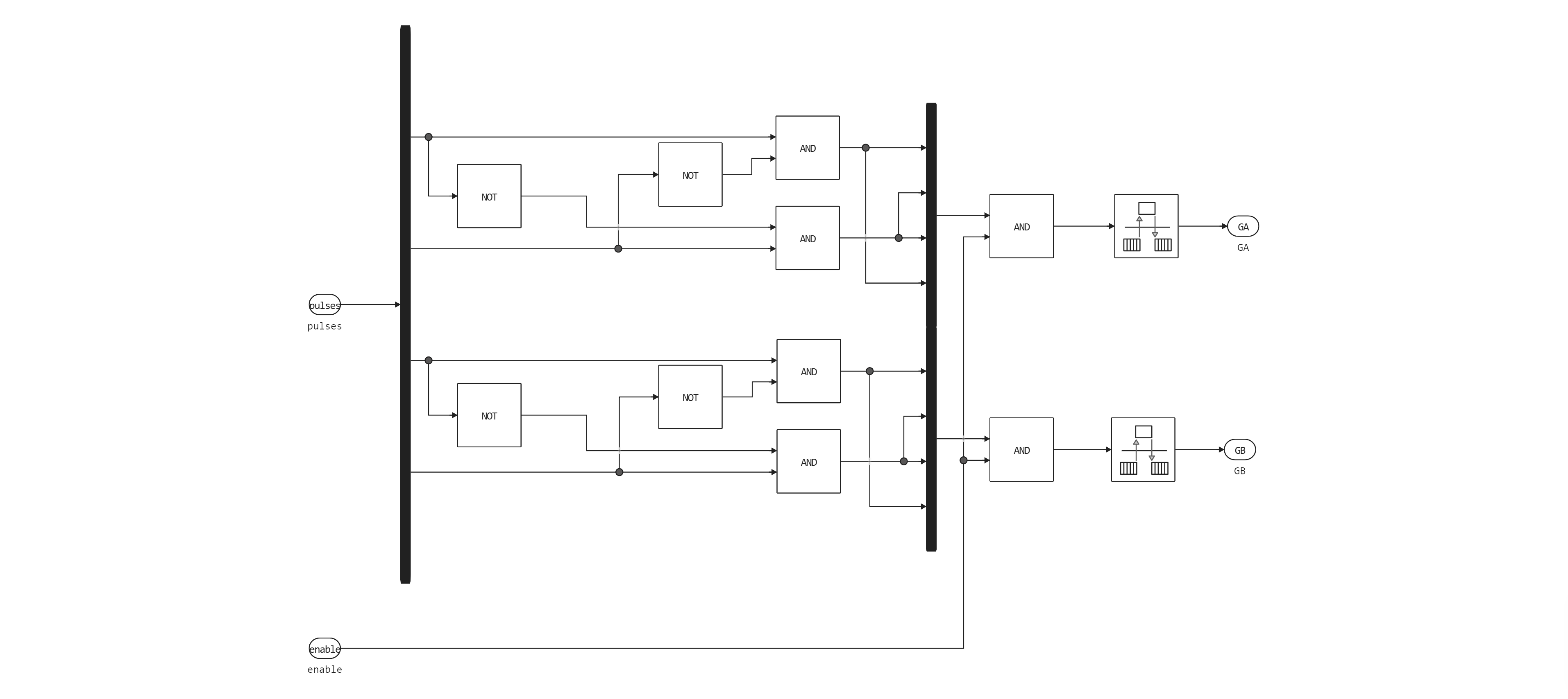
Also, the enable output signal controls the state of the key elements of the inverter: if it is equal to a logical zero, then the inverter is turned off.

The counter subsystem implements an engine phase switching counter. In our example, we use full-step control, in which one phase is activated in one step.
Counter Period It is determined by the formula:
where — the angle of rotation of the shaft in one step, deg; — the required rotation speed, rpm; the formula also contains numerical coefficients: 4 is the number of engine phases, 6 is the conversion coefficient from rpm to deg/s.
By = 300 rpm = 4 ms, which means the phase switching frequency is 1 kHz.

The following phase switching sequence is implemented in the phase_control subsystem:
| Phase | A+ | A- | B+ | B- |
|---|---|---|---|---|
| 1 | 1 | 0 | 0 | 0 |
| 2 | 0 | 0 | 1 | 0 |
| 3 | 0 | 1 | 0 | 0 |
| 4 | 0 | 0 | 0 | 1 |

Inverter control
The Gate Driver subsystem is designed to convert motor phase control signals into control signals for key elements of the inverter.
The inverter
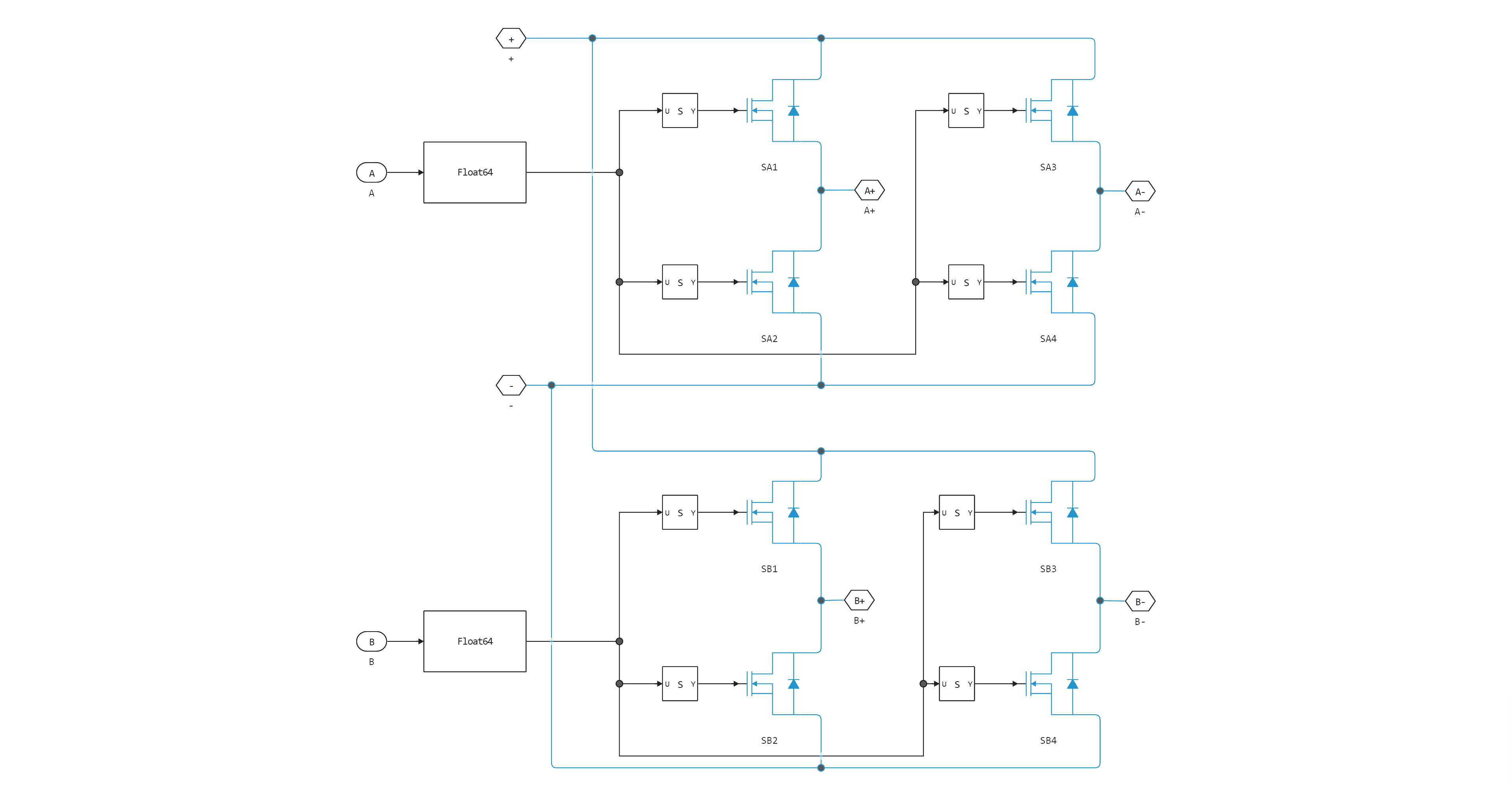
Two two-rack inverters are used to control the stepper motor. The key elements are field-effect MOSFETs. (MOSFET).
Model launch and simulation results
Downloading the necessary libraries:
using Plots
using DataFrames
plotlyjs();
Launching the model:
modelName = "sm_fullstep_control";
if modelName ∉ getfield.(engee.get_all_models(), :name)
    engee.load( "$(@__DIR__)/$(modelName).engee");
end

model = engee.run(modelName);
Reading data on instantaneous values of voltages and currents, as well as rotation speed and shaft position:
t = model["Speed"].time;
Ia = model["Ia"].value;
Ib = model["Ib"].value;
Va = model["Va"].value;
Vb = model["Vb"].value;
Speed = model["Speed"].value;
Position = model["Position"].value;
Plotting the shaft position:
plot(t, Position, layout = (2,1), ylabel = "Position, degree", legend = :none)
plot!(t, Speed, subplot = 2, ylabel = "Скорость вращения, рад/с", xlabel = "Time, c", legend = :none)
Plotting phase currents and voltages:
plot(t, [Va Vb], label = ["Va" "Vb"], ylabel = "Phase voltages, In", color = [:red :blue], layout = (2,1), subplot = 1)
plot!(t, [Ia Ib], label = ["Ia" "Ib"], ylabel = "Phase currents, A", xlabel = "Time, c", color = [:green :black], subplot = 2)
Conclusion
In this example, we examined the implementation of the bipolar stepper motor full-step control algorithm and made sure that it functions correctly.
In the next step, we will generate the code for the STM32 microcontroller and test the control algorithm with a real motor.