Speed control of the simplified synchronous generator
This example demonstrates the behavior of a three-phase, four-wire simplified synchronous alternator when switching loads in a network at:
-
The presence of a rotation speed controller
-
Constant torque — without speed control
General view of the model
The model is based on the library block Simplified Synchronous Machine. A simplified synchronous generator with a capacity of 2000 kVA (1600 kW with a power factor of 0.8), 600 V, 1500 rpm is connected to an active-inductive load with a capacity of 1600 kW and 400 kvar. The neutral point of the stator winding of the machine is grounded. The internal resistance of the generator (Zg = 0.0036 + j0.16 oe) is the resistance of the armature winding Ra and the transient reactance X'd. The inertia constant of the generator is H = 0.6 s, which corresponds to J = 67.5 kg*m^2.
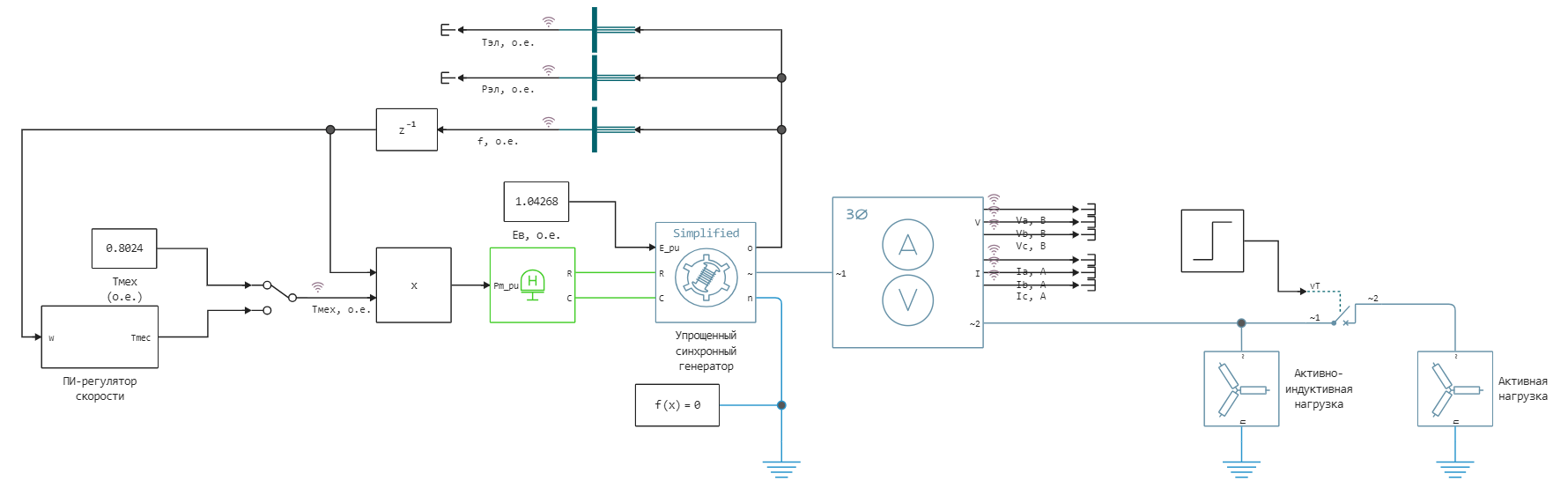
The model provides for switching between a constant torque Tmex and a PI-speed controller. Speed control is modeled using mathematical directional blocks that implement a PI controller. The synchronous machine has a constant voltage across the excitation winding.
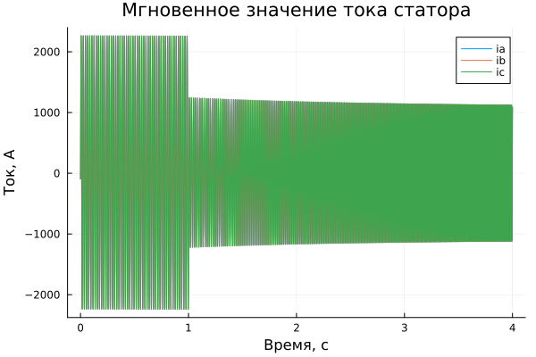
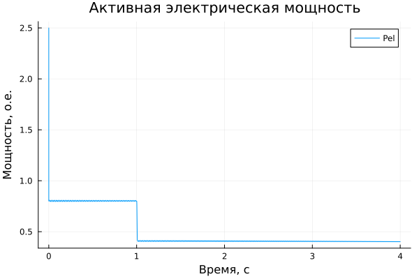
A three-phase switch is used to turn off an 800 kW active load. Initially, the switch is closed and opens at time t = 1 s, which leads to a 50% reset of the active load.
Implementation of the model launch using software control:
Downloading the necessary libraries to import current versus time:
using DataFrames
gr()
Running the model without speed control
Make sure that the Manual Switch is in the position of receiving the signal from the Constant - Tmex unit (OE). By default, the model is already in this position.
Loading the model:
model_name = "ssm_speed_regulation"
model_name in [m.name for m in engee.get_all_models()] ? engee.open(model_name) : engee.load( "$(@__DIR__)/$(model_name).engee");
Launching the uploaded model:
results = engee.run(model_name)
Simulation results
Importing simulation results:
simulation_time = results["Ia, А"].time;
ia = results["Ia, А"].value;
ib = results["Ia, А"].value;
ic = results["Ia, А"].value;
f = results["f, о.е."].value;
Pel = results["Pэл, о.е."].value;
Tel = results["Tэл, о.е."].value;
Tmec = results["Тмех, о.е."].value;
Rendering results:
plot(simulation_time ,ia, legend=true, label="ia")
plot!(simulation_time ,ib, legend=true, label="ib")
plot!(simulation_time ,ic, legend=true, label="ic")
plot!(title = "Instantaneous value of the stator current", ylabel = "Current, A", xlabel="Time, c")
plot(simulation_time ,f, legend=true, label="f")
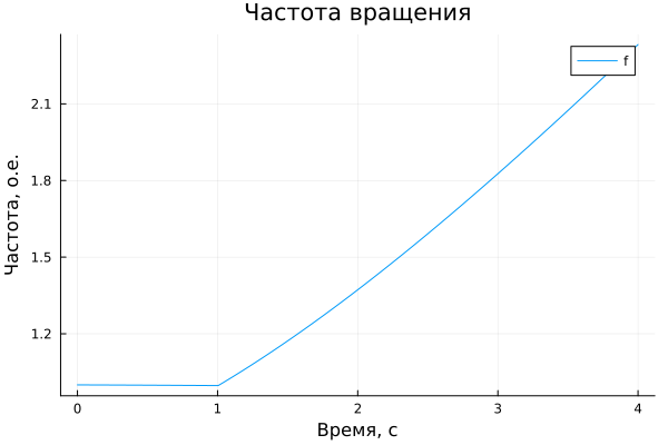
plot!(title = "Rotation speed", ylabel = "Frequency, O.E.", xlabel="Time, c")
plot(simulation_time ,Pel, legend=true, label="Pel")
plot!(title = "Active electrical power", ylabel = "Power, O.E.", xlabel="Time, c")
plot(simulation_time ,Tel, legend=true, label="The electric moment")
plot!(simulation_time ,Tmec, legend=true, label="Mechanical moment")
plot!(title = "Machine Moments", ylabel = "The moment, O.E.", xlabel="Time, c")
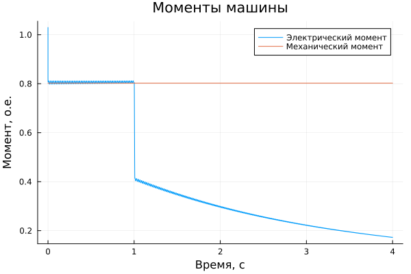
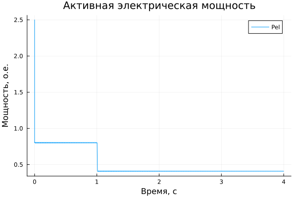
Please note that when the switch opens, the electrical power drops from 0.8 OE to 0.4 OE, and the car begins to accelerate. Since the net electromechanical torque is now equal to:
The speed increase is equal to:
One second after switching at t = 2 s, the expected increase in speed is 0.33 oe. In fact, the speed measured at t = 2 s is slightly higher than the theoretical value (1.374 oe compared to the expected 1.33 oe), since the electrical torque decreases as the speed increases, resulting in an electromechanical torque the moment is above 0.4 oe.
Launching a model with speed control
Now double-click on the Manual Switch block to activate the speed control.
Launching the model:
results = engee.run(model_name)
Simulation results
Importing simulation results:
simulation_time = results["Ia, А"].time;
ia = results["Ia, А"].value;
ib = results["Ia, А"].value;
ic = results["Ia, А"].value;
f = results["f, о.е."].value;
Pel = results["Pэл, о.е."].value;
Tel = results["Tэл, о.е."].value;
Tmec = results["Тмех, о.е."].value;
Rendering results:
plot(simulation_time ,ia, legend=true, label="ia")
plot!(simulation_time ,ib, legend=true, label="ib")
plot!(simulation_time ,ic, legend=true, label="ic")
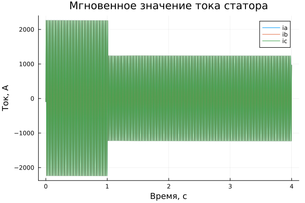
plot!(title = "Instantaneous value of the stator current", ylabel = "Current, A", xlabel="Time, c")
plot(simulation_time ,f, legend=true, label="f")
plot!(title = "Rotation speed", ylabel = "Frequency, O.E.", xlabel="Time, c")
plot(simulation_time ,Pel, legend=true, label="Pel")
plot!(title = "Active electrical power", ylabel = "Power, O.E.", xlabel="Time, c")
plot(simulation_time ,Tel, legend=true, label="The electric moment")
plot!(simulation_time ,Tmec, legend=true, label="Mechanical moment")
plot!(title = "Machine Moments", ylabel = "The moment, O.E.", xlabel="Time, c")
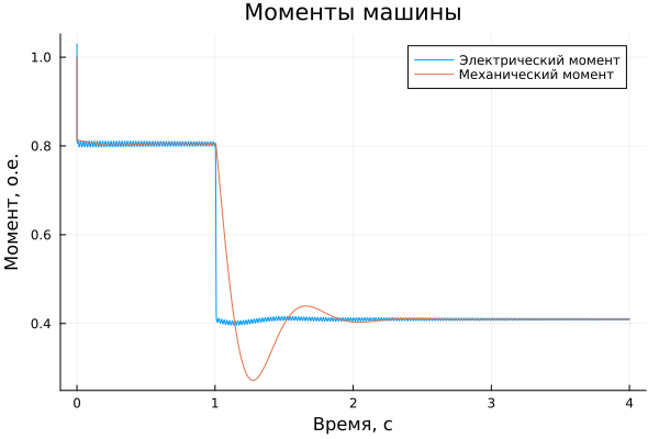
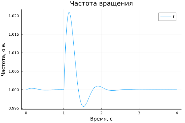
Please note that in order to maintain the speed at its reference value (1 oe), the regulator has reduced the mechanical torque to 0.4 oe.
Conclusions:
In this example, the operation of a simplified synchronous machine unit under disturbance with and without speed control was shown. Tools for command control of the model were used, and the simulation results were imported into a script and visualized using graphs from the Plots library.